Learn · Electrical
Separately Derived Systems
Part of Journeyman Electrician Exam Prep · step 18 of 73 · next: Ampacity
Part of Master Electrician Exam Prep · step 11 of 12 · next: Where to Take the Master Exam
In learning paths: Journeyman Electrician Exam Prep · Master Electrician Exam Prep
Assumes you know: Bonding at Service Equipment, How Transformers Work
A separately derived system is a wiring system whose power comes from a source with no direct electrical connection to the circuit conductors of any other system: a transformer secondary is the everyday example. Because its winding is a brand-new source, none of the building’s existing grounding does anything for it. Fault current returns to the winding that produced it, so a new source means building the entire grounding and bonding story again: a new system bonding jumper, a new grounding electrode conductor, at one new point.
Why it matters on the job
Install a 480 V to 208/120 V transformer to feed office loads and you have created a system as electrically separate from the service as the utility’s transformer is. A fault on the 208 V side cannot be cleared by anything on the 480 V side’s grounding, because 208-side fault current physically cannot return to the utility winding: transformers pass energy through a magnetic field, not through wire. Every rule you learned at the service now replays at the transformer, and the electrician who wires the secondary like a subpanel, neutrals isolated, no bond, builds a system that cannot clear a fault at all.
The service story, replayed at the source
System bonding jumper. The new secondary neutral, X0 on a wye, must be bonded to the equipment grounding system, the mirror of the main bonding jumper. It is installed at exactly one point: at the transformer or at the first disconnect, never both. Two bonds put normal neutral current onto conduit and building steel in parallel with the neutral, the same violation as a bonded subpanel.
Grounding electrode conductor. The new system gets its own GEC, run from the same point where the system bonding jumper lands, to the building’s grounding electrode system, in practice usually the nearest of building steel or metal water pipe that connects to it. New system, new earth reference, same shared electrode system.
Supply-side bonding jumper. Between the transformer enclosure and the first disconnect, fault current has no breaker on the secondary side ahead of it, so the conductor that bonds enclosure to disconnect is a supply-side bonding jumper, sized from the derived-system conductors, not from any overcurrent device.
Not everything with a winding qualifies. A generator whose transfer switch swaps the neutral along with the hots creates a separately derived system, and gets bonded like one. A generator whose transfer switch leaves the neutral solidly connected to the service neutral does not, and must not be bonded again, or the two sources’ grounding systems weld into a parallel-path fault hazard.
Worked example
A 45 kVA, 480 V delta to 208Y/120 V transformer feeds a new panel 10 ft away.
- Secondary conductors sized to the load: 4/0 copper from X0 and phases to the panel.
- System bonding jumper at the transformer: X0 to the transformer case. Sized from the 4/0 derived conductors on the service-conductor table: 2 AWG copper.
- GEC from X0 to the building steel that ties to the electrode system: same table, 2 AWG copper.
- At the new panel: neutrals isolated, grounds on the enclosure, exactly like any subpanel, because the one bond already lives at the transformer.
- Sanity check: a 120 V fault in the new panel now runs EGC, supply-side bonding jumper, system bonding jumper, X0, and the winding drives hundreds of amps through it. Before step 2 existed, that same fault had no return path at all: not weak, absent.
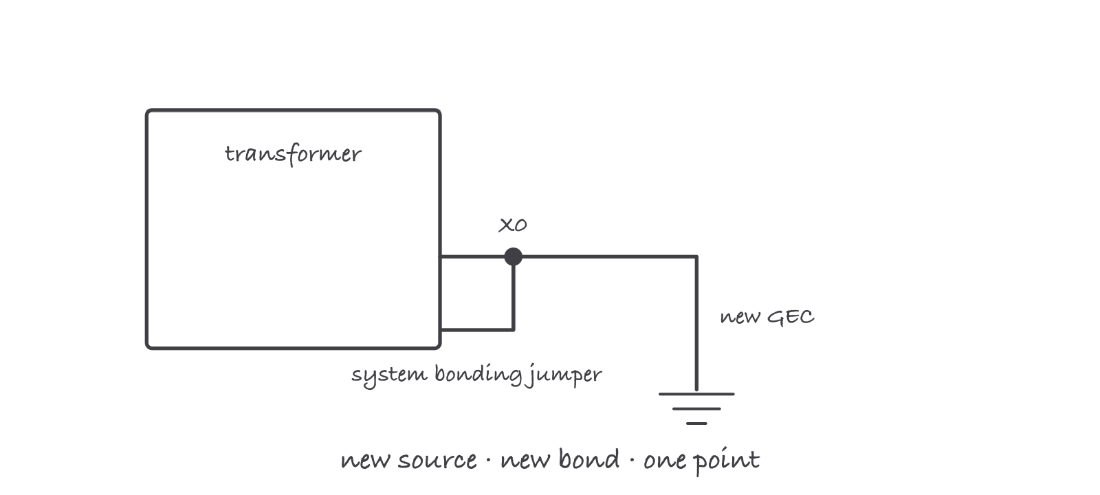
A transformer secondary is a brand-new source, so the whole service story replays in miniature: one system bonding jumper, one new GEC, at one point
Where it bites
- The unbonded secondary is the killer defect. A transformer wired with no system bonding jumper runs perfectly and cannot clear a single ground fault. Meggers and multimeters will not flag it; only checking for the bond will.
- Bonding at both the transformer and the first disconnect is the opposite failure: neutral current on the raceway between them, all day, every day.
- Generator transfer switches decide the grounding, not the generator. Switched neutral: separately derived, bond it. Solid neutral: not separately derived, do not bond it. Wiring the generator before reading the transfer switch is guessing.
- Corner-grounded deltas and ungrounded legacy systems are still separately derived when created anew; the bonding rules adapt but never disappear.
Exam relevance
Master exams lean on separately derived systems heavily: definition questions built on the “no direct electrical connection” test, the one-point rule for the system bonding jumper, and sizing items for the system bonding jumper and GEC from derived-conductor size. The generator transfer-switch question, which configuration is separately derived, is close to guaranteed. Journeyman exams touch the transformer case; masters should be able to trace the full secondary fault path from memory, including why the utility’s grounding contributes nothing to it.
Verified requirements
| Where | Expires | Renewal | Continuing education |
|---|---|---|---|
| Texas | Yes | 1 year | 4 hours per annual renewal cycle |
Information comes from issuing-authority sources. Confirm current rules, fees and eligibility with the authority before acting.