Learn · Electrical
Variable Frequency Drives
Assumes you know: Motor Starting Methods
A variable frequency drive controls a motor’s speed by manufacturing its own AC at whatever frequency the process needs. Since an induction motor’s speed is locked to supply frequency, Ns = 120 × f / P from How Motors Work, a drive that can output 43.7 Hz owns the motor’s speed completely. The VFD is simultaneously the most capable starting method and the most capable speed control in the trade.
Why it matters on the job
VFDs have swallowed a huge share of motor control: fans and pumps for energy savings, conveyors for process speed, compressors for soft loading. Master-level electricians install them, parameterize them, and troubleshoot around their quirks, and the quirks are real: a VFD changes what “normal” looks like on every meter reading downstream of it.
Three stages inside
- Rectifier: converts the incoming fixed-frequency AC to DC.
- DC bus: capacitors smooth and store that DC. This is also why a drive stays lethal after disconnection: the bus holds charge. Honor the manufacturer’s stated discharge wait time before touching conductors.
- Inverter: fast-switching transistors chop the DC into a train of voltage pulses, pulse-width modulation, whose average traces an AC waveform of any frequency and amplitude the drive chooses. The motor’s inductance smooths the pulses into usable current.
Because the drive rebuilds the waveform from scratch, it can start a motor at a few hertz and walk the frequency upward, keeping current near nameplate FLA through the whole acceleration. Inrush, the villain of Motor Starting Methods, never happens.
Volts per hertz: the ratio that protects the motor
A motor’s magnetic flux is set by the ratio of voltage to frequency. Drop the frequency without dropping the voltage and the flux climbs until the iron saturates and the motor cooks. So below base speed the drive holds volts per hertz constant: half frequency, half voltage, same flux, full torque available. Above base frequency the voltage cannot rise further, so flux and available torque fall off, the field-weakening region, usable but weaker.
For fans and centrifugal pumps, slowing down pays outrageously well: by the affinity laws, flow tracks speed but shaft power tracks the cube of speed, which is why VFD retrofits on ventilation systems fund themselves.
Worked example
A 460 V, 60 Hz, 4-pole motor on a VFD. Base ratio: 460 / 60 = 7.67 V per Hz.
At 30 Hz the drive outputs 7.67 × 30 = 230 V, and the motor runs near 120 × 30 / 4 = 900 RPM, minus slip.
At 45 Hz: 7.67 × 45 = 345 V, speed near 120 × 45 / 4 = 1,350 RPM.
The payoff on a fan: at half speed, power is roughly (0.5)³ = 12.5% of full-speed power. Slowing a fan to half speed does not halve the energy, it cuts it by nearly ninety percent.
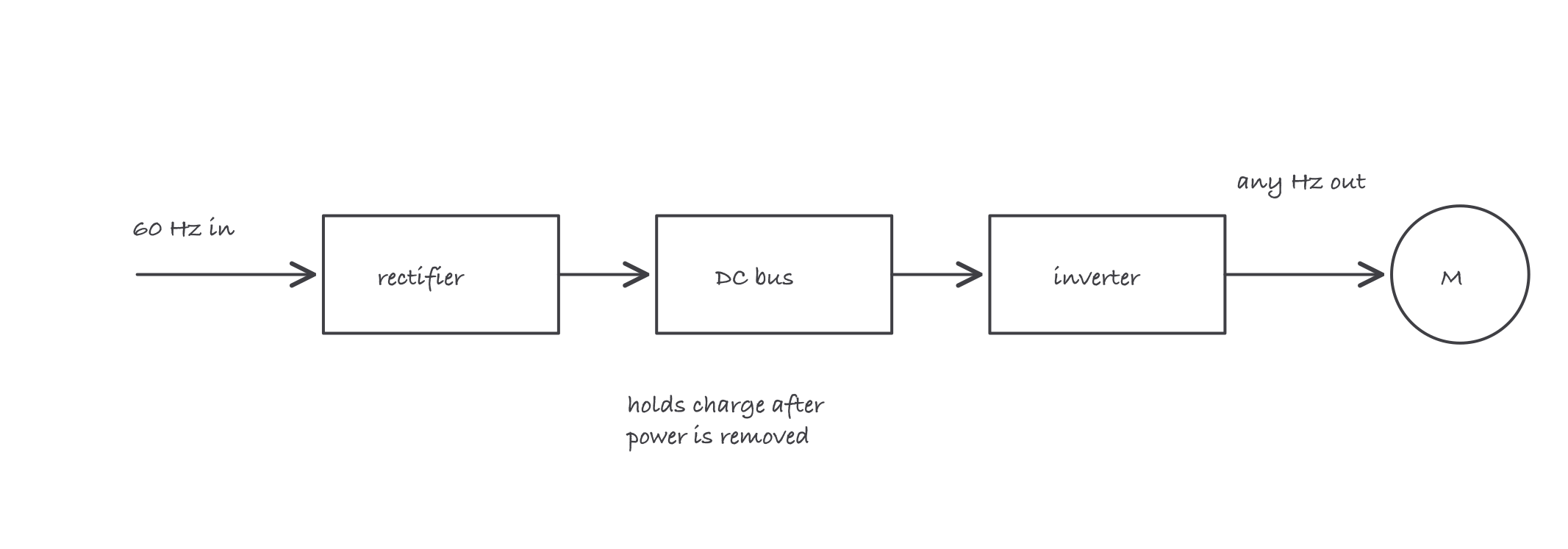
Fixed AC in, DC in the middle, made-to-order AC out: the drive owns frequency, so it owns speed
Where it bites
- The DC bus outlives the disconnect. Charged capacitors hold hazardous voltage after power removal. The wait time printed on the drive is not a suggestion; verify dead before touching.
- Never open the motor circuit while the drive is running. Switching contacts between drive and motor under load can destroy the inverter stage. Control the drive with its inputs, not with a switch on its output.
- Ordinary meters lie about drive output. The output is chopped pulses, not a sine wave; a basic meter’s reading depends on what it assumes. Judge the drive by its own display and use instruments rated for drive waveforms.
- The drive changes the motor’s cooling story. A motor turning slowly turns its own shaft fan slowly too; a heavily loaded motor at low speed can overheat at a current that is otherwise legal. Follow the motor and drive manufacturers’ application limits, including cable-length guidance, and use motors rated for inverter duty where specified.
- A VFD is also a protective device. Its electronic overload and fault trips supplement the scheme from Motor Protection; coordinate them rather than assuming one covers the other.