Learn · Electrical
Feeders
Part of Journeyman Electrician Exam Prep · step 47 of 73 · next: Subpanels
In learning paths: Journeyman Electrician Exam Prep
Assumes you know: Conductor Sizing
A feeder is the set of conductors between the service equipment (or another power source) and the final branch-circuit overcurrent device. Service conductors bring power to the building, feeders move it around inside the distribution system, and branch circuits deliver it to loads. The NEC rules for feeders live in Article 215, with the load calculations that size them in Article 220.
Why it matters on the job
Every subpanel, every detached garage panel, every distribution board in a commercial job hangs on a feeder you size, protect, and pull. Feeder mistakes are expensive in copper and embarrassing in inspections, and unlike a branch circuit, one undersized feeder starves dozens of circuits at once. The classification also decides which rulebook applies: call a run the wrong name and you apply the wrong article.
The three-layer picture
Hold the hierarchy: service conductors → service equipment → feeder → downstream panel → branch circuits. The dividing line on the far end is the final overcurrent device protecting a circuit; everything after that OCPD is branch circuit, everything between it and the source side distribution is feeder.
Feeders are sized the same way branch-circuit conductors are, with the conductor-sizing method you already know from Conductor Sizing: compute the load, apply the continuous-load factor, pick a conductor whose ampacity works at the termination temperature, then protect it at its ampacity. Two feeder-specific habits matter:
Voltage drop. Feeders are long. The NEC’s voltage-drop guidance is informational rather than mandatory in most jurisdictions, but a feeder that arrives 5% low makes every branch circuit on the panel start low. Design practice keeps feeder drop near 3%.
The neutral can be smaller. A feeder neutral only carries the maximum imbalance computed under Article 220, so on big feeders it is often reduced, unlike an equipment grounding conductor, which is sized from the OCPD rating.
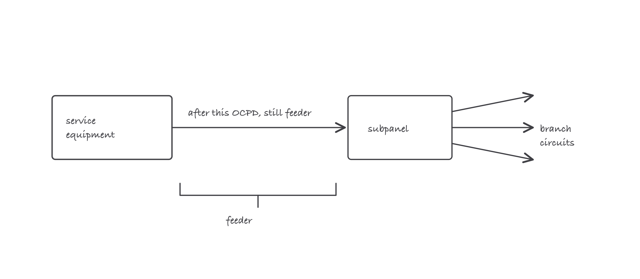
The feeder is the middle leg: after the service disconnect, before the last overcurrent device
Worked example
A 100 A feeder to a shop subpanel, 100 ft of copper in conduit, 240 V single-phase.
Ampacity: Table 310.16 gives 3 AWG copper at 75 °C as 100 A. Terminations on 100 A equipment are typically 75 °C, so 3 AWG works on ampacity.
Voltage drop check: single-phase drop is VD = 2 × K × I × L ÷ CM, with K = 12.9 for copper, I = 100 A, L = 100 ft, and 3 AWG = 52,620 circular mils (Chapter 9, Table 8).
VD = 2 × 12.9 × 100 × 100 ÷ 52,620 = 258,000 ÷ 52,620 = 4.9 V.
4.9 ÷ 240 = 2.0%. Inside the 3% design target, so 3 AWG stands. Stretch the same feeder to 250 ft and the math gives 12.3 V, over 5%: distance, not ampacity, would force the upsize.
Where it bites
- “Subfeed” and “feeder” are the same thing to the Code. There is no separate rule set for feeders that leave a panel that is itself fed by a feeder. Article 215 applies to all of them.
- A feeder OCPD protects the conductor, not the downstream panel’s arithmetic. The feeder breaker is chosen for the feeder ampacity; the downstream panel’s load calculation is a separate Article 220 exercise.
- Voltage drop is design, not (usually) law. Inspectors rarely fail a feeder for drop, customers always notice dim lights and hot motors. Do the arithmetic anyway.
- Taps are the exception zone. Feeder tap rules allow short unprotected-at-ampacity conductors under strict conditions in Article 240. Do not generalize from them; they are narrow exceptions.