Learn · Electrical
How Transformers Work
Part of Master Electrician Exam Prep · step 3 of 12 · next: Transformer Connections (Delta and Wye)
In learning paths: Master Electrician Exam Prep
Assumes you know: Inductance
A transformer moves electrical power between two circuits that never touch, using nothing but a shared magnetic field. AC in the primary winding builds a changing flux in an iron core; the changing flux induces voltage in the secondary winding, mutual induction, exactly the mechanism the Inductance lesson set up. The turns ratio between the windings sets the voltage ratio, and that one fact runs the entire electrical grid.
Why it matters on the job
Every service you connect, every 480 V building with 120 V receptacles, every control circuit and doorbell exists because transformers change voltage almost for free. They have no moving parts, routinely run for half a century, and are among the most efficient machines humans have built. You will size them, connect them, and troubleshoot around them for your whole career, starting from the ratio arithmetic in this lesson.
Turns set voltage, voltage sets current
The primary winding’s turns each share the same core flux, and so do the secondary’s. So voltage divides across turns evenly, and the winding with more turns has the higher voltage, in exact proportion:
Vp / Vs = Np / Ns
More turns on the primary than the secondary: voltage steps down. Fewer: steps up. Same: an isolation transformer, changing nothing but breaking the metallic connection between circuits, which is a safety tool in its own right.
Power, minus small losses, passes through unchanged: what the secondary delivers, the primary draws. Since P = E × I on both sides, current transforms in the inverse ratio: step voltage down 4 to 1 and current steps up 1 to 4. This is why transformer nameplates are rated in kVA, voltage times current, rather than in amps: the amps depend on which side you stand on.
A transformer needs alternating current. Flux that does not change induces nothing: connect a transformer to DC and you get no secondary voltage, just a primary winding with almost nothing limiting its current.
Worked example
A 5 kVA transformer, 480 V primary, 120 V secondary.
Turns ratio: 480 / 120 = 4:1, four primary turns for every secondary turn.
Full-load secondary current: I = 5000 / 120 = 41.7 A. Full-load primary current: I = 5000 / 480 = 10.4 A.
Check the inverse ratio: 41.7 / 10.4 = 4, current stepped up exactly as voltage stepped down. Check power: 480 × 10.4 ≈ 5,000 VA in, 120 × 41.7 ≈ 5,000 VA out. The transformer changed the form of the power, not the amount.
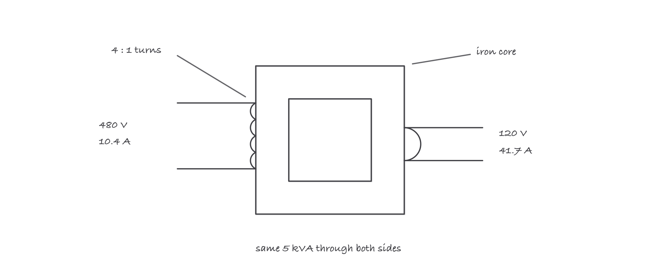
Four turns to one: voltage steps down by the ratio, current steps up by the same ratio, and the kVA passes straight through
Where it bites
- kVA is the rating, amps are a consequence. Asking “how many amps is this transformer” has two correct answers, one per side. Always name the side.
- A transformer is happy to work backward. Feed the low side and the high side becomes the output, which is how step-up connections are made deliberately, and how “dead” secondaries bite people when something backfeeds them. Treat both windings as live until proven otherwise.
- No load does not mean no current. An energized transformer draws a small magnetizing current with the secondary open, and a large magnetizing inrush at the instant of energization, which matters for protection in the sizing lesson.
- The isolation is the point, sometimes. A 1:1 transformer looks useless on paper; it exists to separate a circuit from the grounded system feeding it.