Learn · Electrical
PLC Basics for Electricians
Assumes you know: Relays and Contactors
A programmable logic controller is a small industrial computer that replaces cabinets of hardwired relay logic: field devices wire to its input terminals, loads wire to its output terminals, and the rules connecting them live in software instead of copper. The rules are written in ladder logic, drawn to look exactly like the relay ladder diagrams you already read, which is precisely why electricians take to PLCs faster than programmers do.
Why it matters on the job
Modern machines put the logic in a PLC and leave electricians the parts that still exist physically: sensors, buttons, coils, contactors, and the wiring between them and the I/O terminals. Troubleshooting now means knowing where the boundary is, whether a fault lives in the field wiring, the I/O, or the program, and reading enough ladder logic to follow what the program expects.
The pieces and the scan
A PLC is a power supply, a processor (CPU), and input and output modules. Inputs are the machine’s senses: buttons, limit switches, float switches, each landing on a numbered terminal. Outputs are its hands: signals that drive indicator lamps, relay coils, and contactor coils. An output rated for pilot duty drives an interposing relay or contactor coil, never a motor directly, the lesson Relays and Contactors drew that boundary.
The processor runs an endless loop called the scan cycle: read all inputs into memory, solve the ladder logic top to bottom using those frozen values, then write all outputs at once, and repeat, typically every few milliseconds. The machine responds within a scan or two, faster and more consistently than banks of mechanical relays ever did.
Ladder logic: the diagram becomes the program
Ladder logic keeps the two rails and the rungs. Three instructions cover most of real programs:
- Examine if closed (the NO contact symbol): true when its address is on.
- Examine if open (the NC contact symbol): true when its address is off.
- Output energize (the coil symbol): turns its address on when the rung is true.
The crucial mental shift: program contacts test memory states, not wires. An examine-if-closed instruction is not “a normally open button”, it is the question “is this input on right now?”
Worked example: three-wire control in software
Wire the classic circuit to a PLC: a physically NC stop button to input I1, a NO start button to input I2, and the motor contactor’s coil driven by output O1. One rung: examine-if-closed I1, in series with a parallel pair (examine-if-closed I2, examine-if-closed O1), feeding output O1.
- At rest: the NC stop button holds input I1 on, so its examine-if-closed is true. I2 and O1 are off, so the parallel pair is false. O1 stays off.
- Press start: I2 turns on; the rung goes true; O1 energizes and the contactor pulls in. On the next scan, examine-if-closed O1 is true: the output seals itself in through its own address, the software twin of the auxiliary contact.
- Release start: the seal-in branch holds the rung true. The motor runs.
- Press stop: input I1 turns off, its examine-if-closed goes false, the rung breaks, O1 drops, and the seal-in evaporates. Exactly the three-wire behavior, including staying off after a power cycle if programmed this way.
Notice the trap this example defuses: the stop button is physically normally closed for the same fail-safe reason as ever (a broken stop wire stops the machine), and the program tests it with examine-if-closed, because the healthy, untouched button holds the input on.
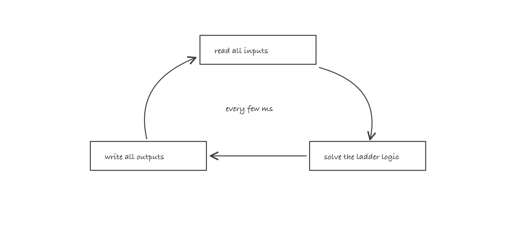
Read, solve, write, repeat: the program sees a frozen snapshot of the inputs each time around the loop
Where it bites
- The NC stop plus examine-if-closed pairing trips almost everyone once. Programming the stop as examine-if-open “because the button is NC” builds a machine that runs only while the stop button is held. Reason from the input’s state, not the symbol on the button.
- Forcing an output bypasses the logic, not the danger. A forced output drives the real contactor no matter what the interlocks say. Forces are a commissioning tool used under control, and every active force is a booby trap for the next shift.
- Indicator LEDs end the argument about where the fault is. Input LED follows the button: field wiring is fine, look in the program. LED dead while the button is pressed: the problem is copper, not code. This one habit sorts most PLC service calls.
- The program you can see may not be the program running. Compare and upload from the processor itself before trusting an old laptop copy; machines get patched at 2 a.m. and files drift.