Learn · Electrical
Series Circuits
Part of Journeyman Electrician Exam Prep · step 6 of 73 · next: Parallel Circuits
Part of Electrical Foundations · step 8 of 19 · next: Parallel Circuits
In learning paths: Journeyman Electrician Exam Prep · Electrical Foundations
Assumes you know: How Ohm's Law Works
A series circuit is a single path: every component strung end to end, one loop, no branches. Two laws govern it completely. The current is the same everywhere in the loop, and the source voltage divides itself across the components. Master those two facts and every series problem, on paper or in a wall, solves the same way.
Why it matters on the job
You will rarely wire loads in series on purpose, but series behaviour finds you anyway. A loose termination is a resistance in series with the load. A long run of undersized conductor is a resistance in series with everything on the circuit. Control circuits, stop buttons, interlocks, and safety switches are deliberately built in series so that any one opening kills the whole path. Reading a series circuit is a diagnostic skill you use weekly, whether or not you ever install one.
The rules
Current is the same at every point. One path means the amps have nowhere else to go. Clamp the loop anywhere and the reading is identical.
Resistances add. Total resistance is the simple sum:
Rt = R1 + R2 + R3 …
Voltage divides in proportion to resistance. Each component drops a share of the source voltage, and the bigger resistance takes the bigger share. The drops always add back up to the source: what the supply provides, the loop spends, exactly.
Power adds too. Each component dissipates its own I²R, and the total equals what the source delivers.
One consequence to hold onto: opening the path anywhere stops everything. That is the weakness of old-style series holiday lights and the entire point of a series safety circuit.
Worked example
A 120 V source feeds a 10 Ω resistance and a 20 Ω resistance in series.
- Total resistance: Rt = 10 + 20 = 30 Ω
- Circuit current: I = E / Rt = 120 / 30 = 4 A, everywhere in the loop
- Drop across the 10 Ω: E = I × R = 4 × 10 = 40 V
- Drop across the 20 Ω: 4 × 20 = 80 V
- Check: 40 + 80 = 120 V, the full source. Nothing missing, nothing extra.
Notice the proportion: the 20 Ω resistance is two thirds of the total resistance and takes exactly two thirds of the voltage. That instinct, resistance share equals voltage share, lets you sanity-check answers without redoing the arithmetic.
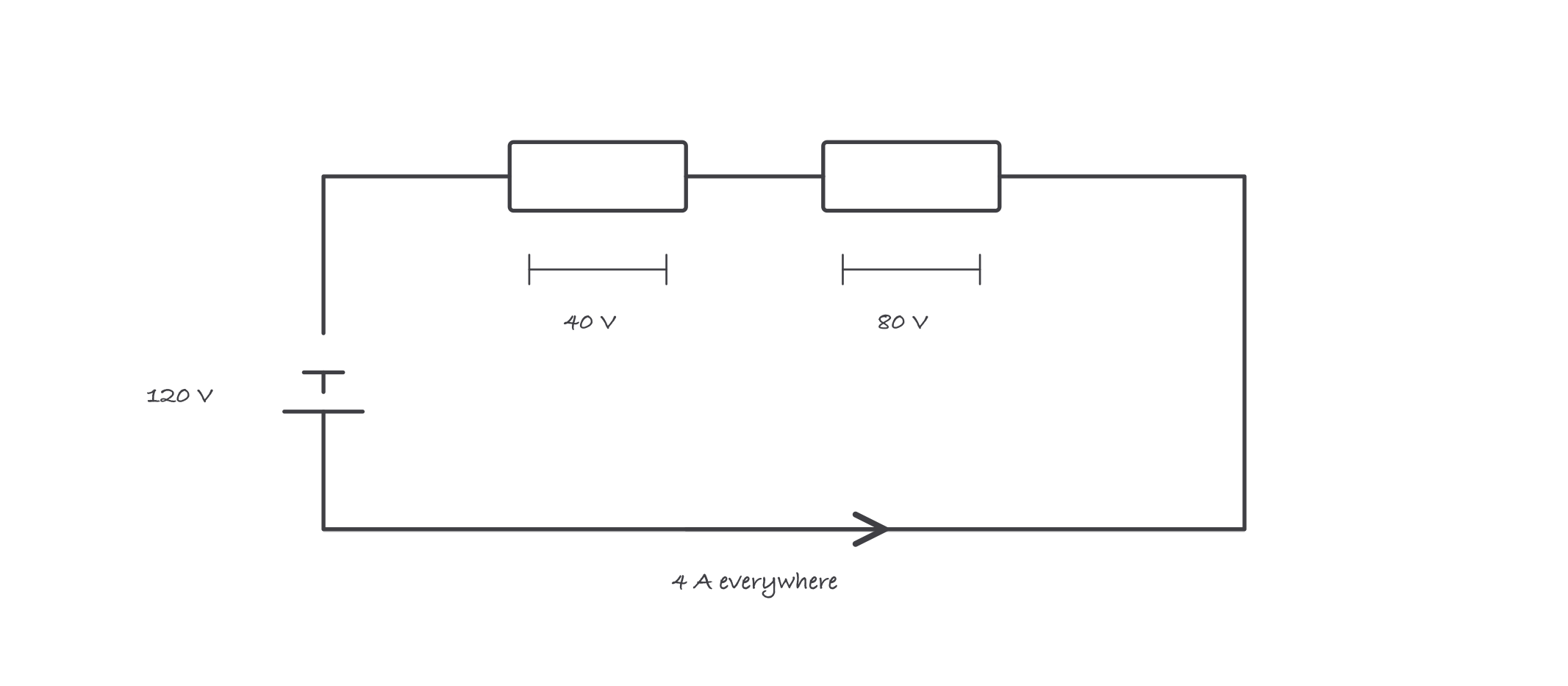
One current, divided voltage: the drops add back to the source
Where it bites
- Using source voltage across one component is the classic error. The 20 Ω resistance above sees 80 V, not 120 V. Ohm’s law always uses the voltage across the thing you are solving.
- A bad connection is an uninvited series component. A corroded splice adds resistance in series, steals its share of the voltage, and turns that share into heat right at the splice. Dim lights and warm devices are series arithmetic announcing itself.
- Voltage drop on long runs is a series problem. The conductor’s own resistance is in series with the load; what the wire drops, the load never receives. The dedicated voltage-drop lesson later builds directly on this page.
- An open anywhere reads full source voltage across itself. With no current flowing, nothing else drops voltage, so the entire 120 V appears across the break. That is why a switched-off switch reads line voltage across its terminals, and why an open is easy to find with a voltmeter.
Exam relevance
Series calculations appear directly, find the current, find a drop, and hide inside voltage-drop and control-circuit questions. Examiners love the open-circuit trap: knowing that full source voltage appears across the open is a reliable mark separator. Drill the proportion instinct; it is faster than the algebra under time pressure.