Learn · Electrical
Single-Phase Motors
Part of Journeyman Electrician Exam Prep · step 56 of 73 · next: How a Three-Phase Motor Works
In learning paths: Journeyman Electrician Exam Prep
Assumes you know: How Motors Work
A single-phase motor cannot start itself: one phase makes a field that pulses along a line instead of rotating, so a stationary rotor feels equal pull in both directions. Every single-phase motor design is a different answer to the same question, how do you fake a second phase long enough to get the shaft moving.
Why it matters on the job
Single-phase motors run the equipment homeowners and light-commercial customers call you about: furnace blowers, well pumps, compressors, garage doors, bath fans. When one hums and trips instead of starting, the fault is almost always in the starting scheme this lesson explains, not in the motor’s guts.
Faking the second phase
Split-phase motors add a second stator winding, the start winding, wound with thinner wire so it has more resistance and less inductance than the run winding. Its current peaks at a different moment than the run winding’s current, and that timing difference is enough of a phase shift to create a weakly rotating field. Once the rotor is up to roughly 75% of full speed, a centrifugal switch on the shaft opens and drops the start winding out; it is a starting device, not a running winding, and it burns up if left in the circuit.
Capacitor-start motors put a capacitor in series with the start winding. The capacitor shifts the start-winding current much further, closer to a true second phase, so starting torque jumps. Same centrifugal switch, same drop-out. This is the design on loads that start hard, compressors and loaded pumps.
Capacitor-start, capacitor-run motors keep a second, smaller capacitor in the circuit permanently for smoother, more efficient running. Permanent split capacitor (PSC) motors use only the run capacitor, no switch at all, fine for easy-starting fan loads. Shaded-pole motors use a copper shading ring on each pole to drag the field sideways, cheap and weak, small fans only.
Many single-phase motors are dual voltage, with two run windings paralleled on the low voltage and put in series on the high voltage, per the connection diagram on the nameplate.
Worked example
A 1 hp split-phase motor. Output is 1 hp = 746 W. At 75% efficiency the electrical input is 746 / 0.75 = 995 W. At a power factor of 0.85 the supply must deliver 995 / 0.85 = 1,170 VA.
On the 115 V connection: I = 1170 / 115 = 10.2 A. Reconnected for 230 V: I = 1170 / 230 = 5.1 A. Same motor, same horsepower, half the line current at the higher voltage, the same trade you saw in Electrical Power.
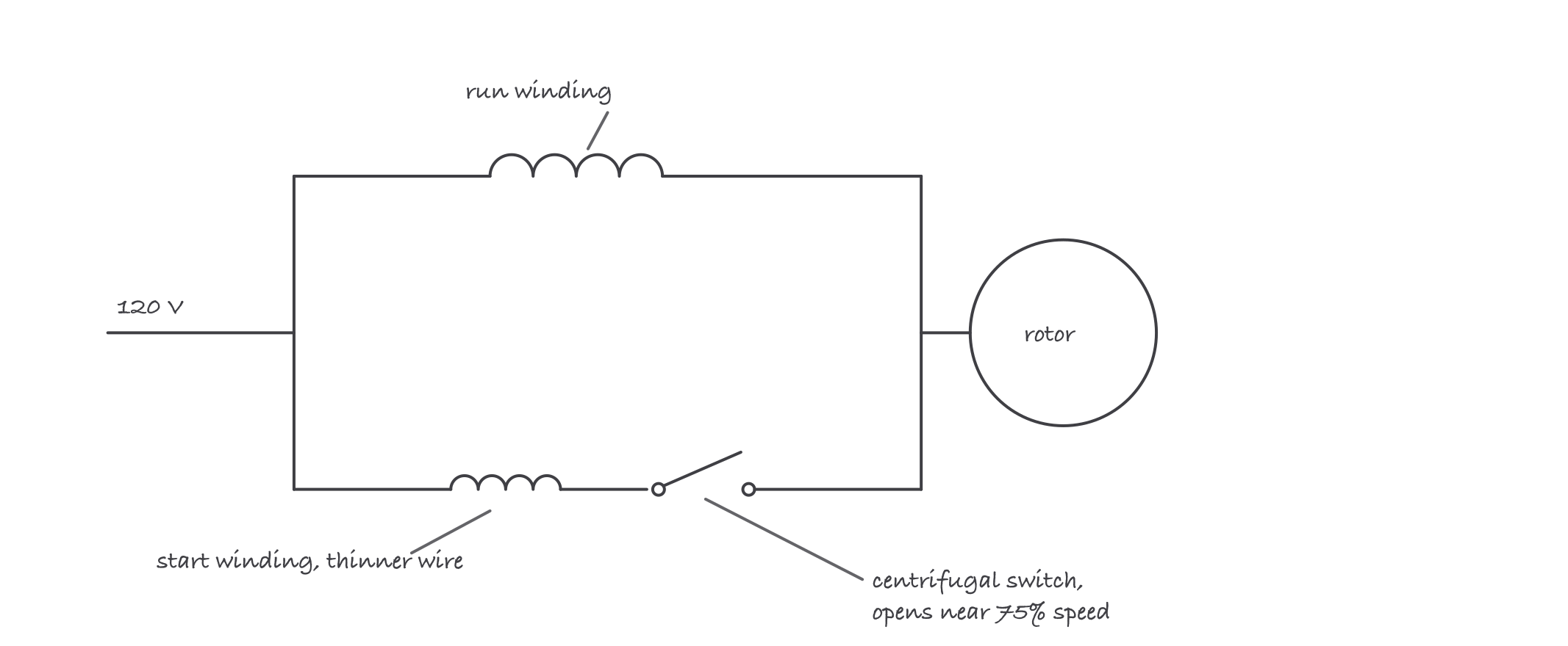
Two windings out of step create the twist to start; the switch dumps the start winding once the rotor is up to speed
Where it bites
- A humming, non-starting motor that spins fine when you flick the shaft has a starting-circuit fault: bad capacitor, welded or dirty centrifugal switch, or an open start winding. The run winding is proving itself fine by running.
- A start capacitor is a short-duty part. If the centrifugal switch fails closed, the start capacitor stays in circuit and fails soon after, often visibly bulged. Replace the capacitor without finding the switch fault and you will be back.
- Start and run capacitors are not interchangeable. Start capacitors are high-microfarad, short-duty electrolytics; run capacitors are lower-microfarad, continuous-duty. Swapping one for the other fails fast.
- Dual-voltage reconnection changes current, not power. Wiring a motor for 115 V and feeding it 230 V does not make it stronger, it makes it smoke.