Learn · Electrical
Relays and Contactors
Assumes you know: Control Circuits
A relay and a contactor are the same idea at two weights: an electromagnet coil that, when energized, physically moves a set of contacts. The coil lives in the control circuit and obeys buttons and switches; the contacts switch some other circuit without any electrical connection to the coil. That separation, small signal in, switched circuit out, is the whole foundation of machine control.
Why it matters on the job
Coils and contacts are what you will actually find behind every panel door: rows of relays doing the logic, contactors doing the lifting. Knowing which is which, how a coil behaves at pick-up, and why contact ratings matter keeps you from the two classic failures: a control transformer that browns out every time a big coil picks up, and a pilot-duty relay welded shut by load current it was never built to break.
One mechanism, two duties
A relay switches small currents: coil circuits, indicator lamps, PLC inputs, interlocks. Its contacts are pilot duty, rated for the modest currents of control wiring. Relays are the logic elements of hardwired control: their contacts appear all over the ladder as the NO and NC symbols you traced in Control Circuits.
A contactor is the heavyweight: large contacts built to make and break load current, motor windings, heaters, lighting banks, with arc-handling built in, because interrupting a loaded circuit draws an arc that must be stretched and quenched. A contactor usually also carries a few small auxiliary contacts that move with the main contacts; the seal-in contact in a three-wire circuit is exactly such an auxiliary.
When a controller’s own output cannot handle a big coil, an interposing relay goes between: the small output drives the relay coil, the relay contact drives the contactor coil.
Coil behavior: inrush and sealed
An AC coil draws its heaviest current at the instant of pick-up, while the magnetic armature is still open, and then drops to a much smaller sealed (holding) current once the armature closes. Coil data lists both as VA. The control transformer must be chosen for the real event: carrying every sealed coil that is normally held in, plus the inrush of the largest coil (or group) that can pick up at the same moment. Sized only for sealed load, the transformer sags at every pick-up, coils chatter, and contacts burn.
Worked example
A 120 V contactor coil is rated 200 VA inrush, 25 VA sealed.
Inrush current: 200 / 120 = 1.67 A. Sealed current: 25 / 120 = 0.21 A, an eight-to-one difference.
A panel holds four such contactors, at most one picking up at a time. Steady load: 4 × 25 = 100 VA. Worst moment: three sealed plus one inrushing = 75 + 200 = 275 VA. The control transformer is selected to deliver that peak without excessive voltage dip, per the manufacturer’s regulation data, not just the 100 VA of quiet running.
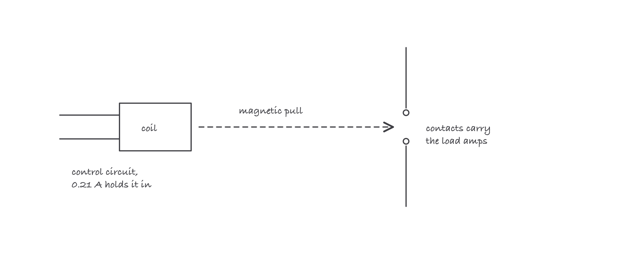
A fraction of an amp through the coil throws contacts that carry the load: the control circuit never touches the power it commands
Where it bites
- Pilot duty is not load duty. A relay contact that “fits” a motor circuit welds or burns because breaking load current draws an arc it cannot quench. Match the contact rating to the duty, not the wire size.
- Chattering usually means starved, not broken. A coil that buzzes and hammers is often fed sagging voltage, an undersized control transformer or a resistive connection, rather than failing itself. A chattering AC contactor also hammers its contacts toward welding.
- A welded contact ignores the coil. If the machine will not stop when the coil drops out, suspect main contacts welded closed; the control circuit can be perfect while the power path stays made. This failure is why stop functions are tested, not assumed.
- Auxiliary contacts are logic, main contacts are power. Landing a control wire on a main pole, or a motor lead on an auxiliary, are both wiring errors the terminal layout will happily let you make.