Learn · Electrical
Power Factor
Part of Electrical Foundations · step 17 of 19 · next: Three-Phase Power
In learning paths: Electrical Foundations
Assumes you know: Impedance
Power factor is the ratio of the power doing work to the power the wiring must carry: watts divided by volt-amperes. On a resistive load the two are equal and the ratio is 1. On motors and other reactive loads, current arrives out of step with voltage, the volt-amperes outrun the watts, and the power factor drops below 1. That gap is not an accounting quirk; it is real current in real conductors doing no work.
Why it matters on the job
Conductors, breakers, and transformers are sized by the current they carry, which follows volt-amperes. Work done, and mostly what is billed, follows watts. At low power factor a facility hauls extra amps through every conductor to deliver the same watts: more heat, more voltage drop, transformer capacity used up by current that accomplishes nothing. Utilities meter it on commercial services and charge penalties below their threshold. When a motor’s nameplate watts and your clamp reading refuse to agree with P = E × I, power factor is the referee.
The concept
The phase shift from the reactance lessons is the cause. Current out of step with voltage still loads the conductors fully, but only its in-step portion delivers energy. That splits power into three quantities:
- True power, P, in watts (W): work actually done. What a wattmeter reads.
- Apparent power, S, in volt-amperes (VA): volts times amps, what the conductors carry.
- Reactive power, Q, in volt-amperes reactive (VAR): energy sloshing to and from fields, doing no net work.
They form the power triangle, the impedance triangle wearing power units: W along the bottom, VAR vertical, VA the hypotenuse. And the ratio is the power factor:
PF = W / VA
PF runs from 0 to 1 and is often quoted as a percentage. Resistive loads sit at 1.0; typical induction motors run roughly 0.8 to 0.9 at full load and worse lightly loaded.
Worked example
A single-phase motor on a 240 V circuit clamps at 10 A. Its nameplate power factor is 0.8.
- Apparent power: S = E × I = 240 × 10 = 2,400 VA
- True power: P = S × PF = 2,400 × 0.8 = 1,920 W
- Reactive power: Q = √(S² − P²) = √(2400² − 1920²) = √(5,760,000 − 3,686,400) = √2,073,600 = 1,440 VAR
Check the triangle: √(1920² + 1440²) = √(3,686,400 + 2,073,600) = √5,760,000 = 2,400 VA. It closes.
Now the cost of the gap: at PF 1.0, delivering 1,920 W at 240 V would need only I = 1920 / 240 = 8 A. The motor draws 10 A instead. Two of every ten amps in those conductors are doing no work, and every conductor, termination, and winding upstream carries them anyway.
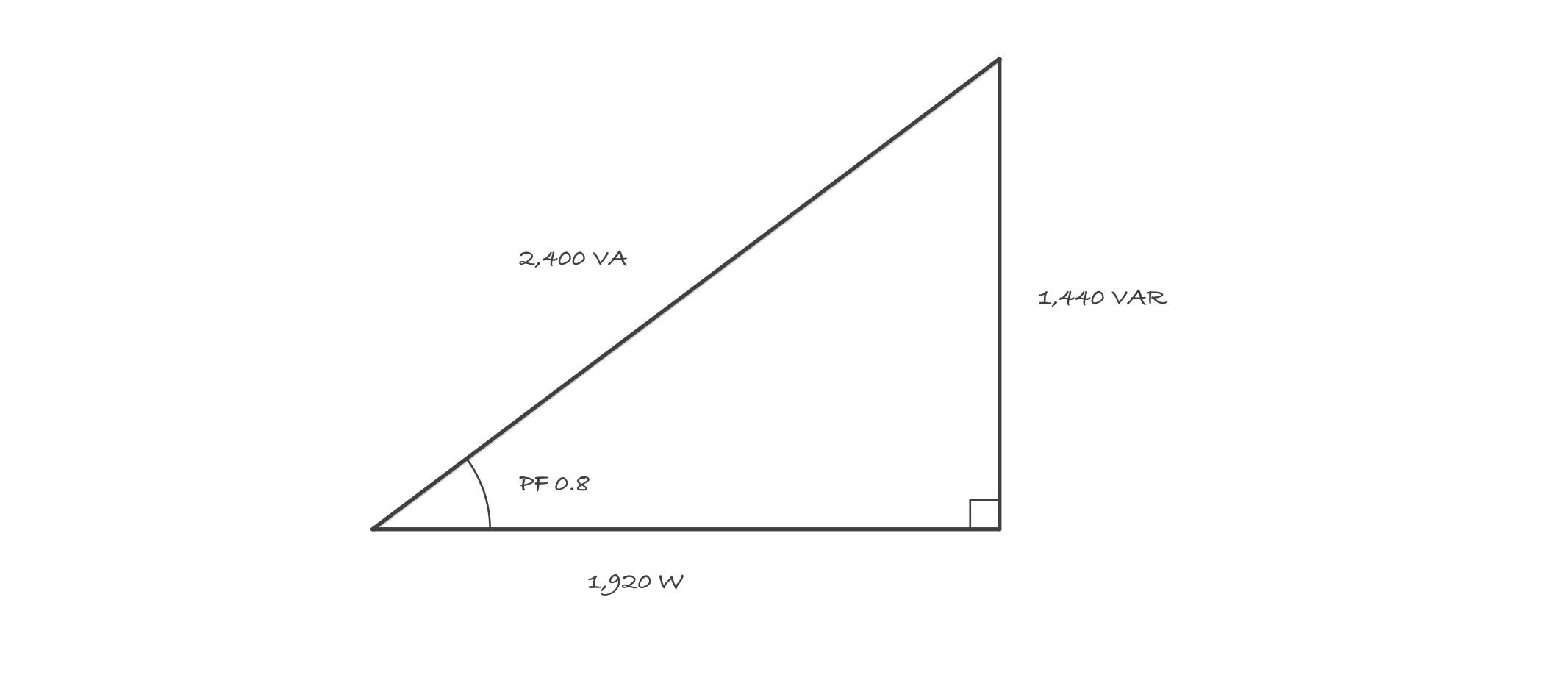
The conductors carry the hypotenuse; the customer gets the bottom side
Where it bites
- W = E × I fails on reactive loads. Volts times amps gives VA, and only PF converts it to watts. Skipping that step overstates motor loads and breaks energy arithmetic.
- Sizing from watts undersizes the wiring. Conductors and OCPD answer to amps, and amps follow VA. A 1,920 W motor at 0.8 PF is a 10 A load, not an 8 A load.
- Correction capacitors are placed, not sprinkled. Capacitive current leads, inductive current lags, so capacitors cancel VAR, that is the fix. But oversized or wrongly placed correction can overcorrect, raise voltage, and on motor terminals cause self-excitation. Correction is an engineered change, not an accessory.
- Low PF hides in light loading. A motor loafing at quarter load can show a dismal power factor even when the full-load nameplate says 0.85. Measured PF beats nameplate PF.
Exam relevance
PF = W / VA and its rearrangements are core journeyman exam material, usually styled exactly like the worked example: two of the three quantities given, find the third, then find the current. The distractor answers come from ignoring PF or applying it in the wrong direction. Sketch the triangle; if the watts came out bigger than the VA, the answer is disqualified before you bubble it.