Learn · HVAC/R
Diagnosing Electrical Problems
Part of HVAC Technician from Zero · step 44 of 49 · next: Diagnosing Refrigerant Circuit Problems
In learning paths: HVAC Technician from Zero
Assumes you know: A Diagnostic Method That Works
Electrical diagnosis in HVAC runs on one fact: a voltmeter across a closed switch reads near zero, and across an open switch in a live circuit it reads full supply voltage, because the meter completes the path through the load. Chase voltage down the circuit until it disappears, and the component where it disappears, or the open that shows full voltage across itself, is your fault. The trade calls the technique hopscotching.
Why it matters on the job
Most HVAC failures are electrical: contactors, capacitors, sequencer contacts, pressure switches, broken splices, cooked terminals. They are also the cheapest faults to fix and the easiest to misdiagnose by parts-swapping. A tech with a schematic, a meter and the hopscotch habit finds an open in minutes, live, without unhooking a single wire. Reading HVAC Schematics and Electrical Fundamentals for HVAC are assumed working equipment here, and A Diagnostic Method That Works supplies the discipline around the meter.
The technique
Work with the schematic in hand and the circuit energized, with the respect live diagnosis demands: rated meter, one hand where possible, dry footing, and no fingers where probes belong.
- Verify supply first. Line voltage at the disconnect and load side of the contactor, control voltage at the transformer secondary. Half of “dead unit” calls are a tripped breaker, a blown low-voltage fuse, or a transformer with primary volts and no secondary.
- Split the circuit. Put one probe on one leg of the supply, hopscotch the other probe point to point along the other leg, across each switch and safety in the ladder, toward the load.
- Read the story. Full voltage to a point, then zero past it: the open lives between those probes. Or read across each device: closed switches read ~0 V, the open one reads full supply.
- Loads get a different question. A load with correct voltage across it that does not run is a failed load (or a seized one): confirm with an amp clamp, then, power off and capacitors discharged, with an ohmmeter.
Worked example: strip heat, one cold stage
An electric furnace from Electric Heat: two 5 kW stages at 240 V, complaint “runs but barely warms”. Amp clamp on the feed: 20.8 A. One 5 kW stage draws 5,000 ÷ 240 = 20.8 A, so exactly one stage is working. Into the cabinet, meter across stage two’s ladder:
- Across the closed disconnect and wiring to the sequencer: supply confirmed, 240 V available.
- Across the sequencer’s stage-two contacts, thermostat calling, warm-up time elapsed: 240 V. A closed switch would read near zero: these contacts never closed. Found it.
- Confirm the rest before condemning: coil side of the sequencer shows 24 V control signal present, so the board and thermostat are doing their jobs; the sequencer itself failed.
- Sanity-check the element it feeds, power off: element resistance R = V² ÷ P = 240² ÷ 5,000 = 57,600 ÷ 5,000 = 11.5 Ω: intact. Replace the sequencer, re-clamp: 41.7 A, both stages pulling their share (10,000 ÷ 240 = 41.7 A).
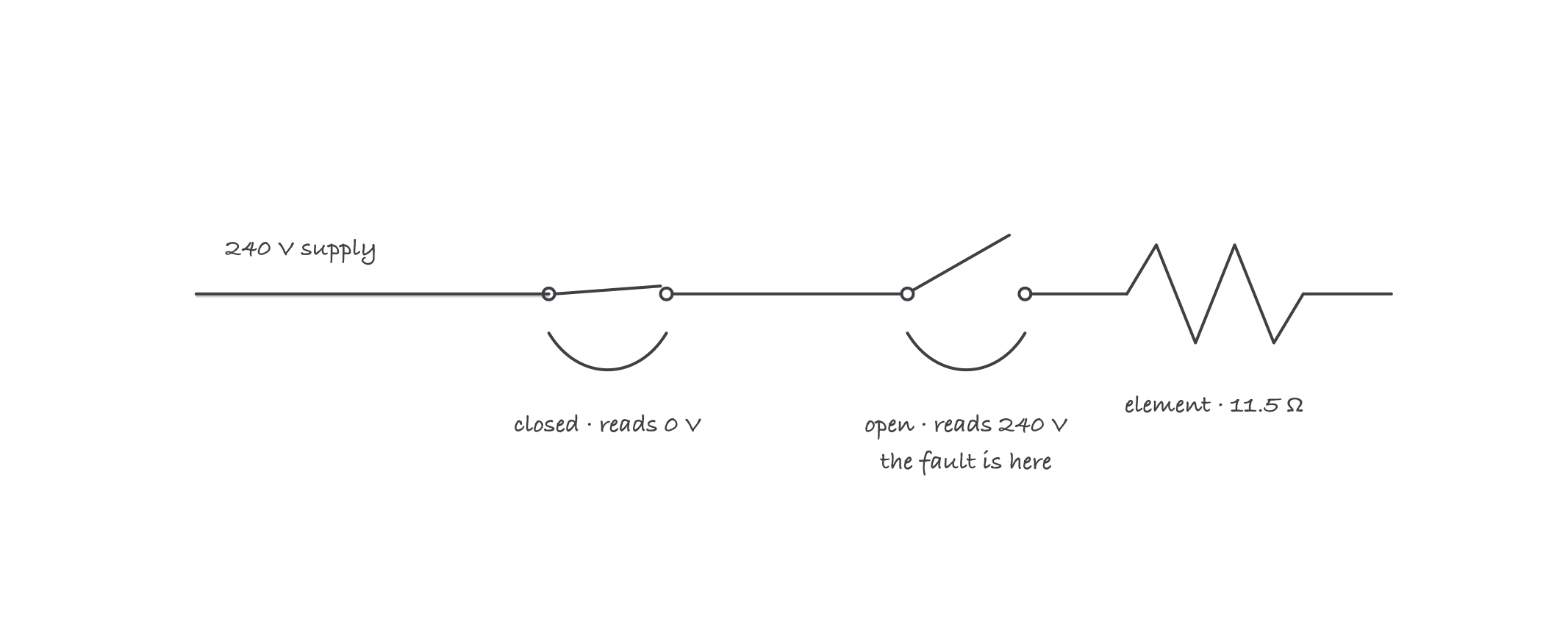
Voltage appears across the thing that is broken: closed contacts read near zero, the failed open reads full supply
Where it bites
- Voltage present is not voltage under load. A burned contact or corroded splice can read 240 V to a high-impedance meter and collapse the moment amps flow. When readings and behavior disagree, test loaded, watch the amp clamp, or use the meter’s low-impedance mode.
- Capacitors bite after the disconnect opens. Discharge before touching, and test suspected capacitors properly: a weak run capacitor drags a healthy motor into looking like a failed one. Capacitors in HVAC has the details, and it is the first suspect on any hard-starting or hot-running PSC motor.
- The safety that opened is a messenger. A high-limit, pressure switch or rollout showing 240 V or 24 V across it has opened for a reason. Find the overheat, the airflow fault or the draft problem behind it; jumping a safety converts a diagnostic result into a hazard.
- Low-voltage shorts blow fuses, not codes. A chafed thermostat wire grounding out takes the 3 A automotive fuse on the board with it. A board fuse that blows again on replacement means find the short, not stock more fuses.
- Ohmmeters lie in-circuit and on live gear. Zero the leads, isolate the component, and never ohm anything energized. Parallel paths through transformers and boards make in-circuit resistance readings fiction.