Learn · HVAC/R
Reading HVAC Schematics
Part of HVAC Technician from Zero · step 21 of 49 · next: Contactors and Relays
In learning paths: HVAC Technician from Zero
Assumes you know: Electrical Fundamentals for HVAC
A ladder schematic is a wiring diagram reorganized so you can think with it. Two vertical rails carry the power source. Every horizontal rung between them is one complete circuit: one load, plus every switch that must close for that load to run. Learn to read one rung and you can read the whole machine.
Why it matters on the job
The pictorial diagram glued inside the panel shows where wires physically go, which helps you find terminals. The ladder shows why the machine does what it does, which helps you find faults. Technicians who diagnose from the pictorial trace spaghetti. Technicians who diagnose from the ladder ask one question per rung: what has to be true for this load to run?
The anatomy of a ladder
The rails are the power supply. On the line-voltage section they are L1 and L2. On the control section they are the transformer secondary: R on one side, C on the other. Everything between the rails operates at that section’s voltage, which is why a good ladder splits into a line-voltage ladder on top and a 24 V ladder below, joined only at the transformer.
Each rung holds exactly one load: a contactor coil, a relay coil, a motor, an indicator light. Switches sit in series with the load on its rung. Two switch symbols carry most of the meaning:
- Normally open (NO): drawn open, closes when its coil energizes or its condition is met.
- Normally closed (NC): drawn closed, opens when actuated. Safety devices are usually NC so a failure breaks the circuit.
“Normally” means de-energized on the bench, not “usually” in operation. The schematic always draws the resting state.
A coil and its contacts share a name but live on different rungs. The contactor coil C sits on a 24 V rung; the contacts labeled C sit in the line-voltage rungs feeding the compressor. Reading a ladder means jumping between rungs by name.
The reading method
- Find the load you care about. Not the wire, the load.
- Read its rung from one rail to the other and list every switch in series.
- For each switch, ask what closes it: a thermostat call, a coil elsewhere in the ladder, a pressure, a temperature.
- Follow those coils to their own rungs and repeat.
You are building a chain of conditions. The fault is the one condition in the chain that is not being met.
Worked example: why won’t the compressor start
The compressor sits on a line-voltage rung behind contacts C. Contacts C close when coil C energizes. Coil C’s rung, on the 24 V ladder, reads: R rail, thermostat Y switch, high-pressure switch (NC), low-pressure switch (NC), coil C, C rail.
The chain of conditions: thermostat calling, both pressure switches closed. At the unit you confirm 24 V from Y to common, so the call is arriving. Meter across the high-pressure switch: 0 V, closed. Across the low-pressure switch: 24 V, open. One rung, three readings, fault found: the same series-circuit logic from the fundamentals lesson, now read straight off the paper.
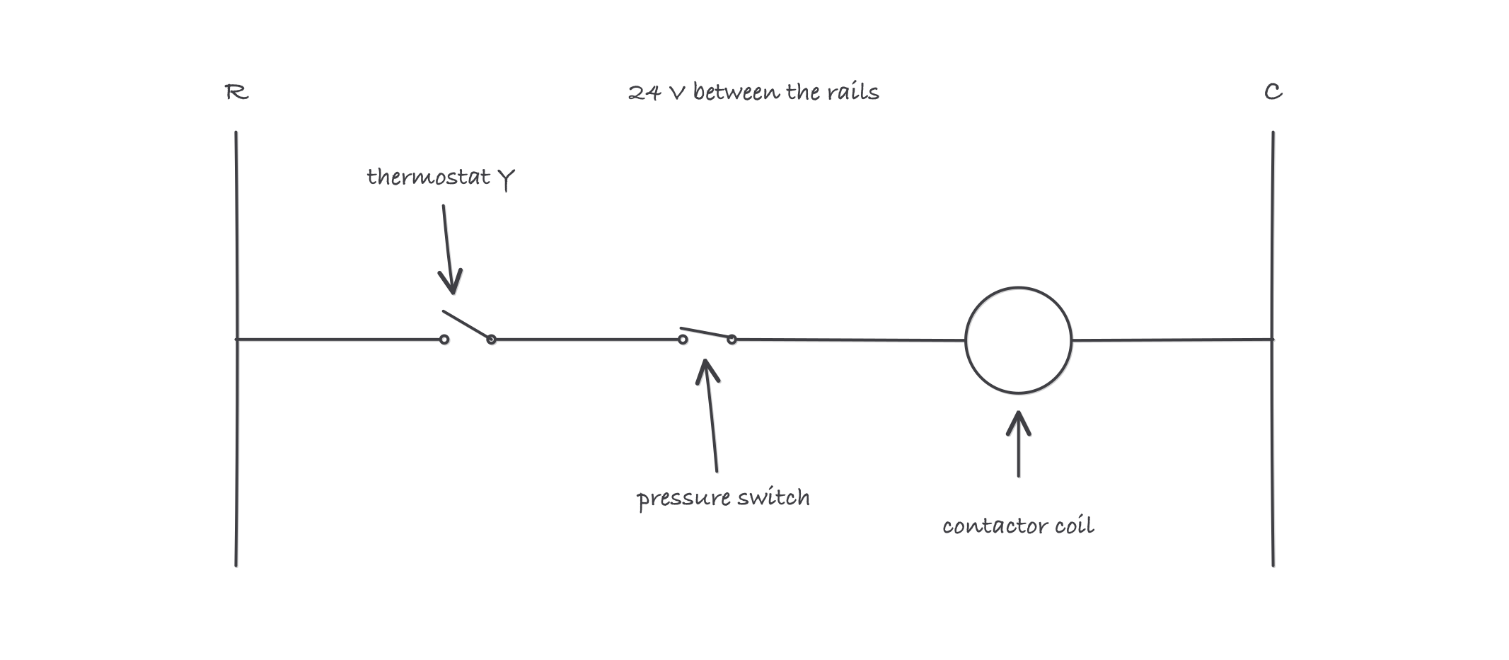
One rung is one question: everything in series with the coil must close before the coil can pull in
Where it bites
- The legend is not optional. Manufacturers reuse letters: C can be contactor, common, or cooling depending on the sheet. Thirty seconds with the legend beats thirty minutes of wrong assumptions.
- Drawn state is de-energized state. A contact drawn open may spend its whole working life closed. Read the ladder as the machine at rest, then energize it in your head.
- Dashed lines mean field wiring or mechanical links. A dashed line between two contacts means one armature moves both. Miss that and the sequence of operations stops making sense.
- The ladder will not show you terminal locations. Use the ladder to decide what to test and the pictorial or connection diagram to find where to put the probes. They are two views of one machine; you need both.