Learn · HVAC/R
Manual J: Calculating the Load
Part of HVAC Design Fundamentals · step 6 of 9 · next: Manual S: Selecting the Equipment
In learning paths: HVAC Design Fundamentals
Assumes you know: Why Load Calculations Exist
Manual J is the procedure that turns a house into two numbers. Feed it the building and a design condition, and it returns the heating load and the cooling load in Btu per hour, with the cooling load split into sensible and latent. The current version is the 8th edition, designated ANSI/ACCA 2 Manual J - 2016, and it covers single-family detached homes, small multi-unit structures, condominiums, town houses and manufactured homes.
Why it matters on the job
The calculation is the document. When an inspector asks how the equipment was sized, the answer is a Manual J output with the inputs attached, and the inputs are what make it defensible: the same house calculated with guessed insulation values and a made-up leakage rate produces a confident-looking number that is wrong. Manual J is also where the duct design starts, because a room-by-room run gives each room its own airflow target.
What it asks for
The inputs are the job. Get them from the building, not from assumption:
- Design conditions for the location, outdoor and indoor, summer and winter
- Construction details for every assembly: walls, roof, ceiling, floors and foundation
- Fenestration with orientation and shading, because a west window and a north window of identical size are not the same load
- Infiltration, measured or estimated by a defined method rather than picked
- Internal loads and occupancy
- Duct characteristics and location, since duct in an unconditioned attic is part of the load
The method inside is the CLF/CLTD approach, and it accounts for heating, cooling, infiltration, ventilation, internal loads and duct effects in one framework.
Whole house or room by room
A whole-house run sizes the equipment. A room-by-room run sizes the equipment and gives every room a CFM target, which is what duct design consumes. If duct work is in scope, the room-by-room run is not optional detail: it is the input to the next step.
Worked example
Ventilation air at a summer design condition, showing why the cooling number has two halves. The house brings in 60 CFM of outdoor air. Outdoor air is 25F warmer than the indoor set point and carries 40 grains per pound more moisture:
- Sensible: Q = 1.08 x 60 x 25 = 1,620 Btu/h
- Latent: Q = 0.68 x 60 x 40 = 1,632 Btu/h
- Total for that 60 CFM: 1,620 + 1,632 = 3,252 Btu/h, of which slightly more than half is moisture
The 1.08 and 0.68 are the sea-level constants for sensible and latent heat in an air stream. A machine chosen only on total capacity has no idea that this load is half latent, and that is the gap Manual S exists to close.
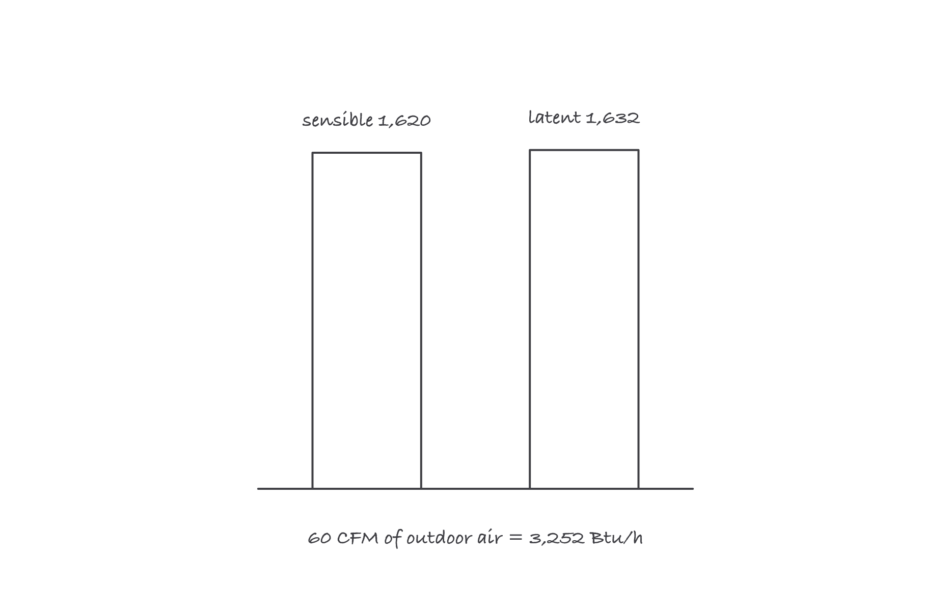
Same air, two loads: the moisture half is invisible on a thermostat and it is half the work
Where it bites
- Guessed inputs produce confident wrong answers. The output carries no warning that the R-value was assumed. Record where each input came from, because that record is what survives a challenge.
- A whole-house run cannot size a duct system. Without the room-by-room numbers there is no per-room CFM, and the duct design that follows is back to rules of thumb.
- “The software did it” is not a method. Approved software implements the procedure; it still takes the orientation, the shading and the leakage from whoever typed them in.
- Design conditions are local and directional. Using a neighboring city’s numbers, or summer design values for a winter run, moves the answer more than most construction details do.
Where the detail lives
The tables, correction factors and the full procedure are in the purchased manual and in the software ACCA approves against it. Naming the standard and the edition is the useful part of a summary; reproducing its values from memory is how a wrong number gets built into a job.