Learn · HVAC/R
Manual D: Sizing the Ducts
Part of HVAC Design Fundamentals · step 8 of 9 · next: What Oversizing Actually Costs
In learning paths: HVAC Design Fundamentals
Assumes you know: Manual S: Selecting the Equipment
Manual D sizes every duct in the system against one governing number: the static pressure the blower actually has left over for ductwork. It is the ANSI-approved standard for residential duct design, and its logic runs in one direction, from the equipment’s pressure budget down to the diameter of each run.
Why it matters on the job
A duct system is a pressure budget being spent. The blower is rated to deliver its airflow at a stated total external static pressure, the coil and filter and accessories take their share off the top, and whatever remains is what the ducts may consume. Size the ducts as though the whole budget were available and the installed system runs above its rating, moves less air than the design assumed, and hands back the comfort problems the load calculation was supposed to prevent.
The four steps
1. Available static pressure. Start from the equipment’s rated total external static pressure (the same TESP measured in the field with a manometer) and subtract the pressure drop of every component in the air path: coil, filter, accessories, balancing dampers, registers and grilles per their published data. What is left is available static pressure, the ducts’ share.
2. Total effective length. Measure the longest supply run and the longest return run, then add the equivalent length of every fitting on those paths. Elbows, takeoffs, boots and transitions each behave like a length of straight duct, and on a typical residential system the fittings contribute more than the straight duct does.
3. Friction rate. Divide the available static pressure across that length: friction rate = available static pressure x 100 / total effective length, expressed in inches of water column per 100 feet.
4. Size each duct at that friction rate. Enter the friction chart or duct calculator with the run’s CFM and the friction rate, and read the diameter. Every duct sized at the same friction rate loses pressure at the same rate per foot, which is what makes the system balance by design instead of by damper.
Worked example
Air handler rated to deliver design airflow at 0.50 in. w.c. total external static pressure. Component pressure drops from the manufacturers’ data: cooling coil 0.10, filter 0.12, balancing damper 0.03. Longest supply path measures 190 effective feet, longest return path 130 effective feet:
- Component total = 0.10 + 0.12 + 0.03 = 0.25 in. w.c.
- Available static pressure = 0.50 - 0.25 = 0.25 in. w.c.
- Total effective length = 190 + 130 = 320 ft
- Friction rate = 0.25 x 100 / 320 = 0.078 in. w.c. per 100 ft
Every run in this system gets sized at 0.078. Notice how little slack there is: the components took half the budget before a single duct was drawn, and a high-resistance filter swapped in later takes its extra straight out of the ducts’ share.
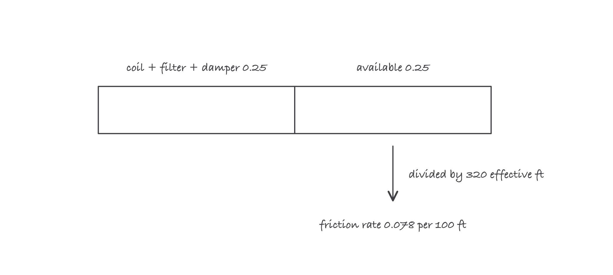
The budget decides the friction rate, and the friction rate decides every diameter in the house
Where it bites
- Straight length is not effective length. A design that measures tape distance and ignores fitting equivalents can understate the path by more than half, producing ducts that are too small at the friction rate they were supposedly sized for.
- The return is half the system. Undersized returns show up as high negative static, and the return path is the half a rushed design leaves out.
- Flex duct has to be installed the way it was sized. The friction data assumes it is pulled tight and fully extended. Compressed flex behaves like a much smaller duct and no design survives it.
- A later filter upgrade spends someone else’s budget. Moving to a higher-resistance filter after commissioning takes its pressure drop out of the ducts’ available static, and the system quietly leaves its design point.
Where the detail lives
The friction chart, the fitting equivalent-length tables and the limits Manual D places on friction rate and velocity are all inside the purchased standard. Those tables are the part of duct design nobody reconstructs from first principles on a job site, which is why a shop that designs duct owns a copy or the software built on it.