Learn · HVAC/R
VRF and VRV Systems
Part of Commercial HVAC Systems · step 4 of 10 · next: Air-Handling Units
In learning paths: Commercial HVAC Systems
Assumes you know: Ductless Mini-Splits
A variable refrigerant flow system connects one or more variable-capacity outdoor units to multiple indoor fan coils on a shared refrigerant network. Each indoor zone is controlled independently while the outdoor equipment responds to the combined demand.
Why it matters on the job
A complaint in one room can originate in that indoor unit, the shared piping and communication network, or the outdoor unit serving every zone. VRF diagnosis requires you to see both the branch and the whole network.
One refrigerant circuit, many zones
Federal equipment definitions distinguish VRF by a common refrigerant circuit, multiple independently controlled indoor fan coils, variable capacity with at least three steps, and a common communications network. The exact equipment arrangement, allowable combinations, piping lengths, branch components, and charge procedures remain manufacturer-specific.
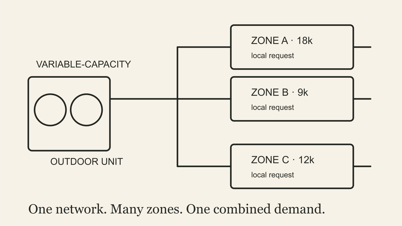
Each zone makes a local request, but the outdoor unit answers the combined system demand
Some systems provide cooling or heating to the connected zones in one mode. Heat-recovery arrangements can move heat between zones with different needs. Do not infer the arrangement from the brand name or cabinet shape. Read the piping diagram and the active control state.
Diagnose from local to shared
For one uncomfortable zone, begin with the local facts: setpoint, mode, sensor value, fan operation, filter, coil condition, electronic expansion device command, and error history. Then compare that zone with others on the same system.
If several indoor units fail together, move outward to shared power, communications, outdoor-unit status, refrigerant conditions, and system-wide limits. A communication address or configuration error can look mechanical because it changes what the refrigerant controls are allowed to do.
Worked example
At one instant, three zones have illustrative cooling loads of 18,000, 9,000, and 12,000 Btu/h.
- Combined demand: 18,000 + 9,000 + 12,000 = 39,000 Btu/h
- If the 9,000 Btu/h zone becomes satisfied, the remaining demand is 18,000 + 12,000 = 30,000 Btu/h
- Demand has fallen by 39,000 − 30,000 = 9,000 Btu/h
The outdoor unit can reduce capacity as zones become satisfied. This arithmetic describes the changing load, not permission to select equipment. Actual diversity, connected capacity, minimum output, pipe sizing, and operating limits come from the manufacturer’s design process.
Where it bites
- A local symptom can have a shared cause. Compare other zones before replacing an indoor component.
- The communications network is part of refrigeration control. Confirm addressing, wiring, and active fault history.
- Connected load is not the same as simultaneous load. Use the manufacturer’s combination and diversity rules.
- Field piping decisions are not generic. Branch devices, lengths, elevation, oil return, pressure testing, evacuation, and charging follow the listed system documentation.