Learn · HVAC/R
Electrical Fundamentals for HVAC
Part of HVAC Technician from Zero · step 18 of 49 · next: Capacitors in HVAC
In learning paths: HVAC Technician from Zero
Every HVAC system you touch is two electrical systems bolted together. Line voltage, typically 120 or 240 V on residential equipment, does the heavy work: it runs the compressor, the fan motors, the electric heat. A 24 V control circuit does the thinking: it carries the thermostat’s decisions to the switches that start those loads. Nearly every electrical diagnosis begins by asking which side of that split you are standing on.
Why it matters on the job
A large share of no-cool and no-heat calls end at an electrical fault, not a refrigerant one. A technician who can hold the line-voltage picture and the control-voltage picture separately in their head finds those faults in minutes. One who cannot ends up swapping parts until something works.
The two-circuit split
The bridge between the two sides is the control transformer. Its primary winding connects to line voltage. Its secondary winding produces 24 V for the control circuit. The two windings are coupled magnetically, never physically, so the control side is its own complete circuit with its own hot leg (called R in most equipment) and its own common (called C).
The control side is all about switches and coils. The thermostat closes a switch; 24 V flows through it to the coil of a contactor or relay; that coil pulls a set of heavy contacts closed. Those contacts live on the line-voltage side, and closing them starts a motor. Small circuit commands, big circuit works.
Loads and switches
Every circuit, on either side, is a power source, a load, and switches in between. A load turns electrical energy into something else: motion, heat, magnetism. A switch just opens or closes the path. Two rules follow that you will use daily:
- A closed switch drops almost no voltage. Measure across it while the circuit is calling and you should read near 0 V.
- An open switch in a live series circuit drops all of it. Measure across the open device and you read full circuit voltage.
That second rule is the fastest fault-finding trick in the trade: the device with all the voltage across it is the one that is open.
Worked example: finding the open in a no-cool call
Outdoor unit dead, indoor blower runs fine. The blower proves the transformer is alive, so the fault is in the cooling path specifically.
- At the transformer secondary, you measure 26.8 V AC. Nominal 24 V systems commonly read 24 to 28 V. Control power confirmed.
- At the outdoor unit, across the contactor coil: 0 V. The coil is not being fed, so the break is upstream of it.
- Work back along the series path. Across the low-pressure switch you read 26.8 V. Full control voltage across one device: that switch is open.
Three readings, no guessing. Now you diagnose why the pressure switch opened, which is a refrigerant question, but the electrical work told you exactly where to look.
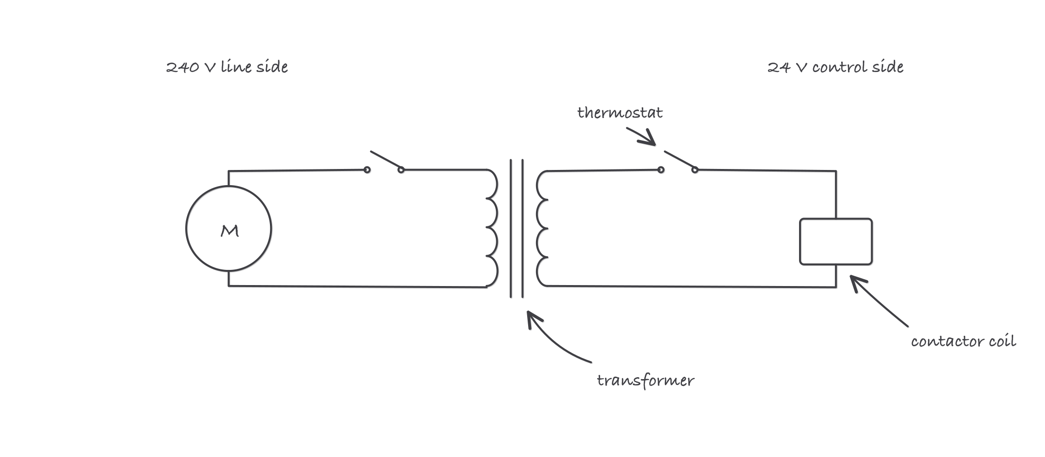
The split that organizes everything: line voltage does the work on the left, 24 V does the thinking on the right, and the contactor is where they meet
Where it bites
- 24 V is not harmless to the equipment. It will not shock you badly, but shorting R to C cooks the transformer or pops the board’s 3 A automotive-style fuse. Kill power before pulling thermostat wires off terminals.
- Two power sources are normal. A split system usually has line voltage at the air handler or furnace and separate line voltage at the condenser. Turning off one disconnect does not make the other side dead. Verify at the unit you are working on.
- The thermostat switches, it does not power. The 24 V originates at the transformer. A dead control circuit with a good thermostat is usually a transformer, fuse, or safety-switch problem.
- Nominal is not exact. Expect 24 to 28 V on a healthy secondary. A reading sagging below about 20 V under load points at a failing transformer or an overloaded control circuit, not a healthy one.