Learn · HVAC/R
Thermostats and Low-Voltage Controls
Part of HVAC Technician from Zero · step 25 of 49 · next: Split System Air Conditioners
In learning paths: HVAC Technician from Zero
Assumes you know: Reading HVAC Schematics
A thermostat is a set of switches between 24 V and the equipment. It makes nothing and powers nothing. R arrives carrying 24 V from the transformer; the thermostat’s only job is to connect R to the right output terminals when temperature says so. Hold onto that and every thermostat problem becomes a switching problem.
Why it matters on the job
Thermostat terminals follow a lettering convention shared across most residential equipment, which is why a technician can walk up to a strange wall plate and know what the wires probably do. Probably. The convention is strong but not law: manufacturers vary, installers improvise, and previous owners re-wire. The pattern gets you oriented; the equipment’s own wiring diagram gets you correct. Verify per equipment, always.
The common pattern
- R: 24 V hot from the transformer. Some stats split it into RC and RH for systems with separate cooling and heating transformers; a factory jumper joins them when there is one transformer.
- C: common, the return path to the transformer. Older mercury and battery stats did not need it; modern powered stats do, because R to C is the 24 V supply the stat itself lives on.
- Y: cooling call. R switched onto Y energizes the outdoor contactor coil.
- G: fan call. R onto G energizes the indoor blower relay.
- W: heat call. R onto W starts the heat sequence, gas or electric.
- O/B: heat-pump reversing valve. O energizes the valve in cooling (most brands); B energizes it in heating (some others). This is the terminal most worth double-checking.
Second stages stack onto the pattern as Y2 and W2. The logic never changes: every call is R connected to a terminal.
Reading calls with a meter
Because the stat is switches, you test it by asking whether the switch closed. Reference everything to C:
- R to C should read 24 to 28 V at all times. No reading here means no control power, and no powered stat will function.
- Y to C reads about 24 V when cooling is being called, 0 V when it is not.
Same for G and W. If the stat closes R to Y but the equipment does not respond, the fault is downstream: wire, safety switch, or coil. If the call never leaves the stat, the fault is the stat, its programming, or its power.
Worked example: tracing one cooling call
Set the stat 5 degrees below room temperature. At the air handler’s terminal strip:
- R to C: 26.4 V. Control power is present.
- Y to C: 26.4 V. The stat has closed R onto Y; the cooling call is real and has crossed the wall wire.
- G to C: 26.4 V, and the blower is running: the stat energizes G together with Y in cooling.
- At the condenser, Y to C: 0 V. The call left the air handler but never arrived. The fault is in the thermostat cable run to the outdoor unit: broken, chewed, or disconnected.
Four readings walked the call from the wall to the break.
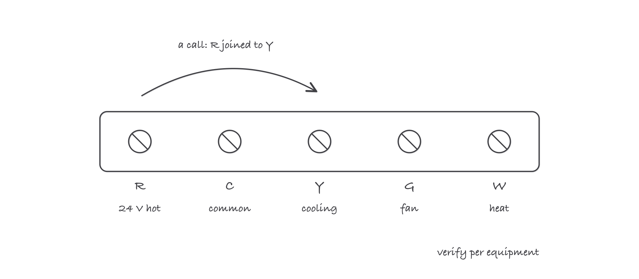
The common pattern: R is the 24 V source, C is the return, and every call is R switched onto another letter
Where it bites
- Letters name conventions, not guarantees. A previous installer may have used the blue wire for Y and the yellow for C. Trust the terminal screws and the diagram, never the wire colors.
- No C wire, no smart stat. Powered thermostats need R and C to live. Power-stealing workarounds exist, but they trickle current through equipment relays and cause ghost behavior. Pull a proper C or use the manufacturer’s adapter.
- O versus B is a heat-pump trap. Wrong reversing-valve logic makes a heat pump cool on a call for heat. Confirm which convention the outdoor unit uses before commissioning.
- Shorted stat wires kill transformers. A staple through the cable or a bared strand at the strip puts R straight to C. If a control fuse blows the moment a call starts, suspect the wire run before the board.