Learn · HVAC/R
Chillers
Part of Commercial HVAC Systems · step 2 of 10 · next: Chilled-Water Pumping
In learning paths: Commercial HVAC Systems
Assumes you know: How the Refrigeration Cycle Works
A chiller removes heat from a building by cooling a water loop. The chilled water carries heat from air-handler coils back to the plant, and the chiller moves that heat into outdoor air or a second water loop that ends at a cooling tower.
Why it matters on the job
A chiller plant spreads one cooling job across several pieces of equipment. The refrigerant circuit can be healthy while poor water flow, a dirty heat exchanger, or a failed tower fan makes the building warm. You diagnose the plant by following heat through all of its loops.
The chilled-water loop
The evaporator is where building heat enters the refrigerant circuit. Chilled water returns from the building, passes through the evaporator, and leaves colder. Pumps send it back to the air handlers, where it absorbs heat from the air and starts the trip again.
Inside the chiller, the same vapor-compression cycle you already know repeats: evaporator, compressor, condenser, and metering device. The scale changes. The physics does not.
Where the condenser sends the heat
An air-cooled chiller rejects condenser heat directly to outdoor air. Its condenser coil and fans are part of the machine, so the plant needs a chilled-water loop but no condenser-water loop.
A water-cooled chiller rejects heat into condenser water. A second pump carries that warmer water to a cooling tower, where the heat leaves outdoors. The plant therefore has 3 connected circuits: chilled water, refrigerant, and condenser water.
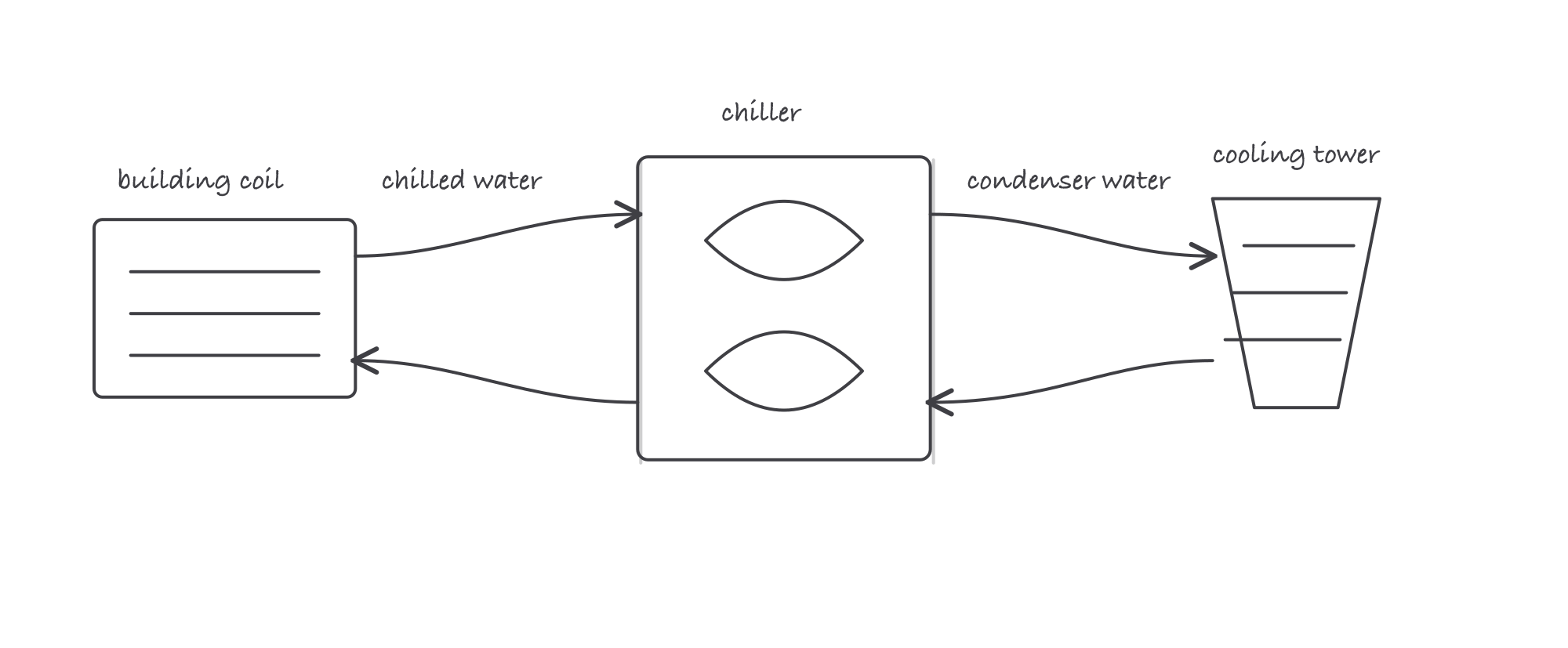
A water-cooled plant moves the same heat through three connected loops
Lift and plant performance
The compressor works against lift, the difference between the evaporating and condensing conditions. Raise the chilled-water temperature or lower the condenser-water temperature within the manufacturer’s operating limits, and the compressor has less lift to overcome.
Heat-transfer surfaces matter for the same reason. Scale or sludge on a tube insulates it, so the refrigerant and water need a larger temperature difference to move the same heat. Air trapped in a condenser raises discharge pressure. Restricted condenser-water flow also pushes the condensing condition upward.
The chiller is only part of the electric load. Chilled-water pumps, condenser-water pumps, and cooling-tower fans all consume power. A plant change that saves compressor power but drives auxiliary power higher must be judged at the plant meter, not only at the chiller display.
Worked example
Compare 2 operating points for an illustrative 400-ton plant. The first point needs 0.60 kW per ton. After cleaning the heat exchangers and restoring the intended water flow, the plant needs 0.50 kW per ton at the same load.
- Before: 400 tons × 0.60 kW/ton = 240 kW
- After: 400 tons × 0.50 kW/ton = 200 kW
- Difference: 240 kW − 200 kW = 40 kW
That comparison does not prove which repair produced the change. It shows how the kW-per-ton metric turns plant performance into a number you can trend at equal load and operating conditions.
Where it bites
- Do not stop at the refrigerant circuit. A clean gauge reading does not clear the water loops, pumps, tower, strainers, or air handlers.
- Do not compare unlike loads. Raw kW falls when load falls. Compare kW per ton at similar conditions or the trend will flatter a plant that is doing less work.
- Lower condenser water is not an unlimited target. The chiller and tower must remain inside their operating limits. The manufacturer’s documentation governs the real machine.
- Fouling creates a temperature problem before it looks like a dirt problem. Trend approach temperatures and pressure conditions so the loss appears before comfort complaints do.