Learn · Plumbing
Reading Plumbing Drawings
Part of Journeyman Plumber Exam Prep · step 5 of 31 · next: Valves
In learning paths: Journeyman Plumber Exam Prep
Assumes you know: How Building Plumbing Systems Work
Plumbing drawings say where every pipe goes before a wall exists, and they say it in three views: the plan view looks straight down, the riser diagram looks at one vertical stack, and the isometric shows the whole three-dimensional run on one flat sheet. Reading them is a lookup skill: symbols from the legend, distances from the scale, heights from the notes and risers.
Why it matters on the job
The rough-in crew works from drawings while the building is bare framing, and a fixture roughed 6 in off its dimension becomes a wall opened later at someone’s cost. Just as important, the drawing is the answer sheet during layout arguments: when the superintendent asks why the closet flange sits where it sits, “the plan dimensions it off this wall” ends the conversation. Plumbers who read drawings fluently get handed layout; plumbers who do not get handed a shovel.
The three views
Plan view is the floor plan with plumbing overlaid: walls, fixtures, and pipe runs seen from above. It locates everything in two dimensions and hides the third almost completely, a vertical stack is a small circle, and a pipe dropping through the floor stops dead.
Riser diagrams rescue the vertical: a flat, not-to-scale sketch of one stack showing what connects at each floor, in order, with sizes.
Isometric drawings show the whole layout in three dimensions at once, using the convention that vertical pipes draw vertical and horizontal pipes draw at 45 degrees, left-running and right-running directions taking the two diagonal families. An isometric of a bathroom group shows every trap, arm, stack connection, and vent takeoff in their real relationships, which is why code exams and journeyman practicals lean on them, and why NCCER has you sketching isometrics early. Learn to draw them, not just read them: an isometric sketch is how plumbers explain layouts to each other.
Line conventions carry meaning too: the legend on each drawing set defines its symbols for fixtures, valves, cleanouts, and pipe services, and different line styles distinguish waste from vent from water. The legend on this job governs, always; symbol habits vary between offices.
Scale: the drawing’s ruler
Plans are drawn to scale, commonly stated like 1/4 in = 1 ft. Read distances with the formula:
Real distance = measured drawing distance ÷ scale factor.
At 1/4 in = 1 ft, every quarter inch on paper is a real foot: divide the measurement in inches by 0.25, or multiply by 4, to get feet. Architect’s scales do the conversion mechanically, but knowing the arithmetic keeps you honest when checking a dimension with an ordinary tape.
Dimensions printed on the drawing always beat distances you scale off it, drawings get reproduced at odd sizes, and printed dimensions survive that when scaled measurements do not.
Worked example: pulling a run length off the plan
The plan is drawn at 1/4 in = 1 ft. You need the length of a straight waste run from the kitchen wall to the stack, and the run is not dimensioned.
- Measure the run on paper: 3 1/2 in.
- Convert: 3.5 ÷ 0.25 = 14 ft of real pipe run.
- Sanity check with the building: the plan shows the run crossing two 4 ft joist bays plus a 6 ft hallway, 4 + 4 + 6 = 14. The scale answer and the building agree.
- Now apply Applied Math for Plumbers: at 1/4 in per ft of slope, that run needs 0.25 × 14 = 3.5 in of fall, a number you now know before a single joist is drilled.
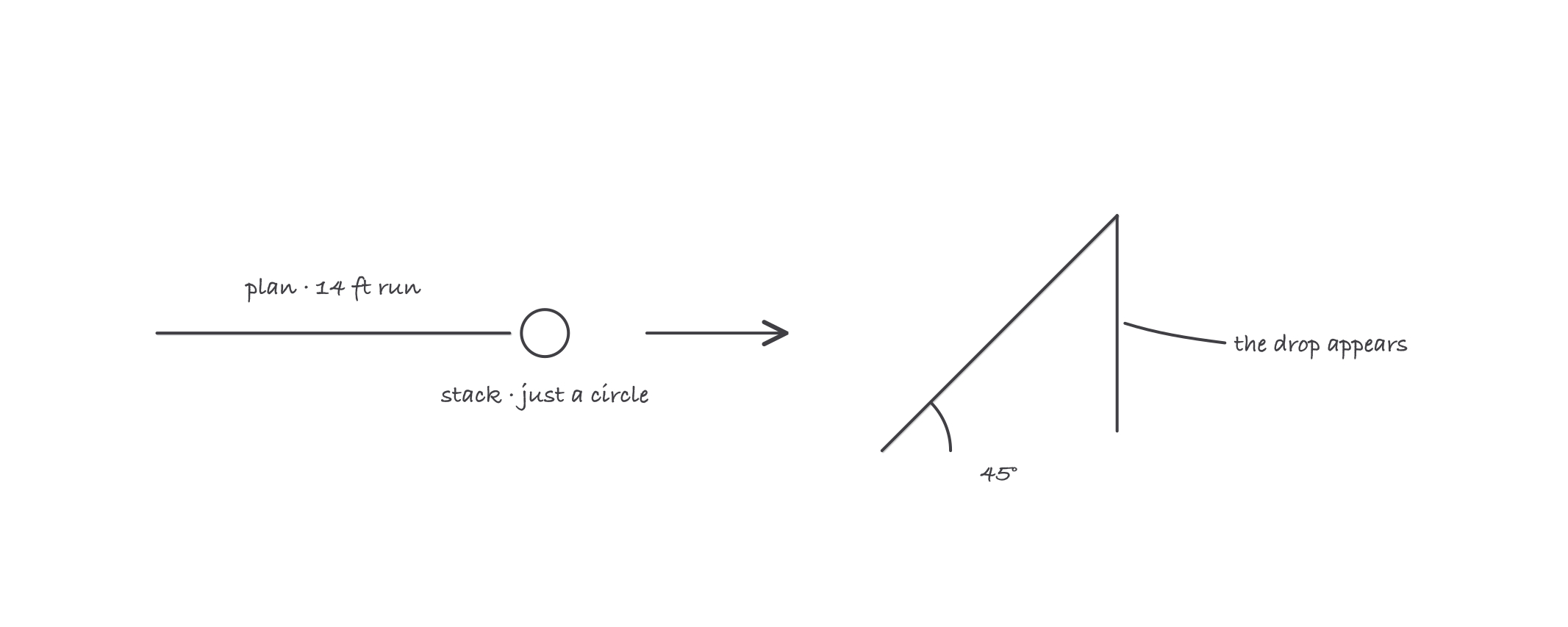
The plan locates the run; the isometric shows what it does in three dimensions
Where it bites
- The plan view hides heights, and heights are half of plumbing. A run that looks clean on plan can be impossible once real joists, beams, and slopes enter. Check the riser and the sections before declaring a route buildable.
- Never scale a photocopied or PDF-printed drawing without checking. Prints get shrunk to fit paper. Verify against a printed dimension or a graphic scale bar before trusting your tape on paper.
- Isometric direction is a convention, not a picture. The 45 degree lines encode direction; they do not preserve true lengths visually, and only labeled dimensions are real. Reading an isometric like a photograph produces confidently wrong takeoffs.
- Legends change between jobs. The symbol that meant a gate valve in the last office’s set can mean something else in this one. Thirty seconds with the legend saves an ordered-wrong valve package.