Learn · Ironworking
Reading Placing Drawings
Part of Ironworker, Steel and Rebar · step 6 of 25 · next: Tying and Splicing Rebar
In learning paths: Ironworker, Steel and Rebar
Assumes you know: Rebar: Grades, Sizes, Placement
Placing drawings are the rodbuster’s set. A detailer takes the structural engineer’s design drawings and turns them into instructions a crew can build from: every bar given a mark, a size, a length, a bend, a quantity and a position. You do not place steel from the engineer’s drawings any more than a connector erects from them.
Why it matters on the job
The placing drawing is the only document that answers the three questions a mat actually poses: what bar, where, and how far apart. It also carries the bar list, which is what the shop cut and bent to. A bundle arriving on site is identified by a mark that means nothing except on this set, so a crew that cannot read the drawing cannot even sort the delivery.
The documents in the set
Placing plans are the plan view of a slab, footing, mat or deck with the bars shown as lines and each group tagged with a callout.
Sections and elevations cut through the member to show the layering: which bars are top, which are bottom, which way the hooks turn, and what cover applies on each face.
The bar list (schedule) is the shop’s table: mark, size, quantity, length, bend type and the dimensions of every bend. It is what you check the delivery against.
Reading a callout
A typical group callout reads like this: 24 - #6 x 14’-6” @ 9” o.c. T&B.
- 24 is the quantity in that group.
- #6 is the bar size, 6/8 of an inch, 0.750 inches in diameter.
- 14’-6” is the cut length of each bar.
- @ 9” o.c. is the spacing, center to center, and it is a maximum rather than a target.
- T&B means top and bottom.
The mark that goes with the group ties it back to the bar list, and the bar list gives the bends. A bar with a mark and no bend dimensions is a straight bar; anything else has a bend detail attached.
Cover and spacing are measured differently
This is the misreading worth being pedantic about.
Spacing is center to center: from the centerline of one bar to the centerline of the next.
Cover is to the face of the bar: from the face of the finished concrete to the nearest surface of the steel, not to its centerline. Cover exists to protect the bar from corrosion and fire and to give it the lever arm the design assumed, so half a bar diameter of sloppiness is a real loss.
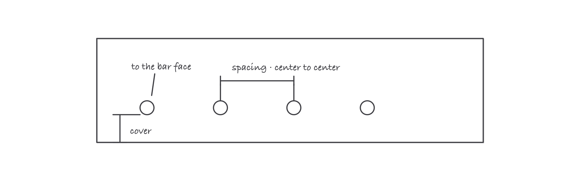
Two dimensions on the same section, taken from two different points on the bar
Required cover comes from the drawings for that job, because it varies with the member, the exposure and the code the project is built to. Chairs, bolsters, wheels and dobies hold it, and they are placed to a spacing of their own so the mat does not sag between supports under a boot.
Worked example
A continuous footing is 40 ft long. The placing drawing calls for #6 @ 9” o.c. transverse, with 3 inches of cover at each end. How many bars, and at what actual spacing?
Start by finding the distance between the centers of the two end bars, because spacing is a center-to-center dimension while cover is to the face of the bar.
- #6 diameter = 6/8 = 0.750 in, so half a diameter is 0.375 in.
- The end bar’s center sits 3 + 0.375 = 3.375 in from the end of the footing.
- Run between the two end bar centers: 480 in − (2 × 3.375) = 480 − 6.75 = 473.25 in.
Now divide by the spacing.
- 473.25 / 9 = 52.58 spaces.
Round up, not to the nearest whole number. The callout is a maximum spacing, so 53 spaces it is, giving 53 + 1 = 54 bars.
- Actual spacing: 473.25 / 53 = 8.93 in, comfortably inside the 9 inch maximum.
Check what rounding the other way would have cost. At 52 spaces the actual spacing is 473.25 / 52 = 9.10 in, which exceeds the specified maximum on every space in the footing. One bar’s worth of steel is what stands between the callout and an inspection failure across a 40 foot pour.
Where it bites
- The engineer’s drawings and the placing drawings can disagree. When they do, that is a request for information. The detailer’s set is a translation, and translations contain errors.
- Round spacing up, round quantity up. Spacing callouts are almost always maximums. Rounding to the nearest whole number is not the same operation and it fails half the time.
- Construction loads are not the crew’s guess. 1926.701(a) requires that no construction loads be placed on a concrete structure or portion of a structure unless the employer determines, based on information received from a person who is qualified in structural design, that the structure or portion is capable of supporting the loads. A mat that looks like a work platform is not one.
- Check the delivery against the bar list before it is spread out. A short bundle found on the drawing is a phone call. The same bundle found at 6 a.m. on pour day is a stopped pour.