Learn · Ironworking
Reading Erection Drawings
Part of Ironworker, Steel and Rebar · step 2 of 25 · next: Structural Bolting
In learning paths: Ironworker, Steel and Rebar
Assumes you know: Structural Steel Basics
Erection drawings are the erector’s set: a framing plan for every floor, an elevation for every column line, a detail for every connection, and a piece mark on every member. They are not the same documents the fabricator worked from and they are not the structural engineer’s design drawings. They are the instructions for putting the pieces together in the field.
Why it matters on the job
OSHA measures your work against this set. 1926.756(a)(1) requires at least two bolts per connection “of the same size and strength as shown in the erection drawings” before the load is released from the hoisting line. Not two bolts you have in your bag: two bolts that match the callout. If you cannot find the callout, you cannot certify that the connection is legal to release.
The four documents you will actually use
Framing plans are the plan view of one floor or roof level, drawn on the column grid. Every member in that level appears as a line with a piece mark next to it. This is where you find out what goes in a bay.
Elevations are the vertical sections along each column line. Columns, splices, bracing and floor elevations live here. When a column is a two-tier or three-tier piece, the elevation shows where the splices land.
Details are the enlarged drawings of individual connections: how many bolts, what diameter, what grade, what type of connection material, and where the field welds go if any.
The erection plan is a different animal. 1926.752(e) allows certain operations only when a site-specific erection plan has been developed, and it must be developed by a qualified person. It is a written safety and sequence document, not a framing plan. Confusing the two in a meeting is a fast way to look green.
Piece marks are addresses
Every shipping piece leaves the shop with a mark painted or stamped on it, and that same mark appears on the framing plan at the place the piece belongs. The mark is what makes shake-out possible: a member on the ground is meaningless until the mark tells you which bay it goes in and which end is north.
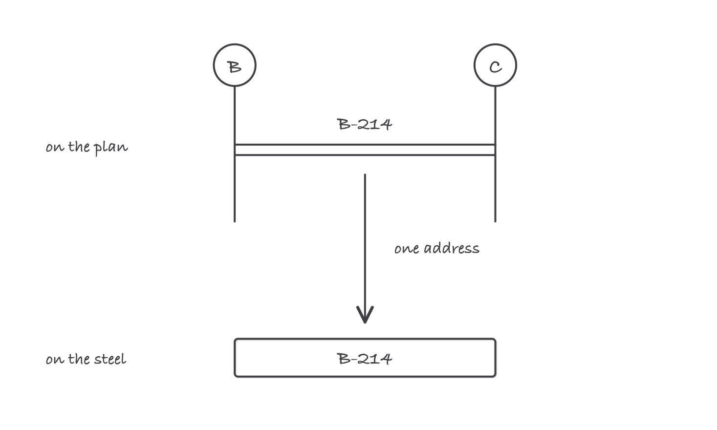
The mark on the steel and the mark on the plan are the same address
Marks are directional. A beam with different connections at each end has a north or a top indicated on the drawing, and hanging it backwards means the holes miss by the difference between the two connection types. That is a re-pick, and on a tight schedule it is an expensive one.
What the controlling contractor owes you first
Before steel starts, 1926.752(a) puts two written notifications on the controlling contractor. It must give the steel erector written notification that the concrete in the footings, piers and walls, and the mortar in masonry piers and walls, has attained either 75 percent of the intended minimum compressive design strength or sufficient strength to support the loads imposed during steel erection. It must also give written notification that any repairs, replacements or modifications to anchor rods have been done in accordance with 1926.755(b).
Those two letters are as much part of the erection paperwork as the drawings. No letters, no steel.
Worked example
Take a beam-to-column detail off the set. The detail shows a shear tab with six 3/4 inch bolt holes, three per row, and calls out six bolts at each end of the member.
Read what that means for the raising gang. Under 1926.756(a)(1) the connectors need at least two bolts per connection, so each end of that beam needs 2 bolts wrench-tight before the hook is released. Two ends means 4 bolts per member before the load line comes off.
Now scale it to the bay. Eight beams of that detail land in the bay today.
- Bolts the connectors must place before releasing loads: 4 × 8 = 32.
- Bolts in the completed bay: 6 per connection × 2 connections × 8 beams = 96.
- Left for the bolting-up gang: 96 − 32 = 64.
That 32-to-64 split is the whole rhythm of a steel job. The raising gang buys stability with a third of the bolts; the bolting-up gang buys the finished connection with the rest.
Where it bites
- Two bolts is a floor, not a spec. 1926.756(a)(2) requires a competent person to determine whether more than two bolts are needed for stability on cantilevered members, and diagonal bracing gets its own lower minimum of one bolt wrench-tight under 1926.756(b).
- Design drawings and erection drawings disagree on purpose. The engineer’s set shows intent and sizes; the erector’s set shows pieces and connections. When they conflict, that is a request for information, not a judgment call at the hook.
- Column tops are drawn with a safety dimension. 1926.756(e) requires perimeter columns to extend 48 inches above the finished floor, with holes at 42 to 45 inches to take perimeter safety cables. Those holes are on the drawing for a reason and are not optional detailing.
- A mark you cannot read is a piece you cannot set. Marks get sandblasted, painted over or bent in shipping. Sort it out on the ground with the fabricator’s advance bill, never by measuring the piece and guessing.