Learn · Industrial Maintenance
Pneumatics
Part of Maintenance Tech to CMRP · step 13 of 30 · next: Hydraulic Troubleshooting
In learning paths: Maintenance Tech to CMRP
Assumes you know: Hydraulics Fundamentals
Pneumatics uses the same force law as hydraulics (force equals pressure times area) on a fluid that behaves in one radically different way: air compresses. Everything that makes pneumatics cheap, fast and forgiving comes from that, and so does everything that makes it springy, wasteful and wet.
Why it matters on the job
Compressed air is the utility a plant treats as free and pays for hardest. Getting mechanical work out of it means running a motor, driving a compressor, losing most of the input as heat, drying the air, piping it, and finally regulating it down at the machine. Very little of the electricity that goes into the compressor arrives at the cylinder as work.
That is why compressed air maintenance is dominated by two things that look like housekeeping and are not: leaks and water.
Air compresses, and that changes the design
Oil is effectively incompressible, so a hydraulic cylinder holds position between two closed ports. Air is a spring. A pneumatic cylinder stopped mid-stroke will bounce under a changing load, so pneumatics is at its best driving between hard stops (extended or retracted) and at its worst holding an intermediate position.
Compressibility also means the air in a receiver, a header, and a hose is stored energy in the same sense a hydraulic accumulator is. A pipe that comes apart under pressure whips, and a fitting that lets go becomes a projectile.
The upside is real too. Air is fast, it tolerates being dumped to atmosphere instead of returned to a tank, and a leak makes a mess of nothing. An overloaded pneumatic actuator stalls instead of tearing something apart.
Free air and the compression ratio
Air volume depends on pressure, so a pneumatic volume means nothing until you say at what pressure.
Free air is the volume the same quantity of air would occupy at atmospheric pressure. The compression ratio converts between them:
compression ratio = (gauge pressure + 14.7) ÷ 14.7
At 80 psig that is (80 + 14.7) ÷ 14.7 = 6.44, so one cubic inch of air inside an 80 psi cylinder came from about 6.44 cubic inches of free air at the compressor inlet. Compressor and system capacities are quoted in standard cubic feet per minute (scfm), which is free air, and that is why cylinder sizing always passes through this conversion.
Worked example: what one cylinder costs in scfm
A 3.00 in bore cylinder with a 1.50 in rod, 12 in of stroke, running at 80 psig, cycling 20 times a minute.
Compression ratio. (80 + 14.7) ÷ 14.7 = 6.44.
Extend. Bore area is π ÷ 4 × 3.00² = 7.0686 in², so the swept volume is 7.0686 × 12 = 84.82 in³ at pressure. As free air: 84.82 × 6.4422 = 546.4 in³.
Retract. The annulus is 7.0686 − 1.7671 = 5.3014 in², so 5.3014 × 12 = 63.62 in³ at pressure, which is 63.62 × 6.4422 = 409.8 in³ of free air.
Per cycle. 546.4 + 409.8 = 956.2 in³ of free air.
Per minute. 956.2 × 20 = 19,124 in³/min, and one cubic foot is 1,728 in³, so 19,124 ÷ 1,728 = 11.1 scfm.
One modest cylinder, eleven cubic feet of compressed air a minute. Put twelve of them on a machine and you have the compressor’s whole output. This arithmetic is why adding one more cylinder is a plant-air decision rather than a machine decision.
Now do it at 60 psig instead. The ratio becomes (60 + 14.7) ÷ 14.7 = 5.0816, and the demand falls to 956.2 × (5.0816 ÷ 6.4422) = 754.2 in³ per cycle, which is 754.2 × 20 ÷ 1,728 = 8.7 scfm. A 20 psi reduction cut this cylinder’s air use by about 21%, and the cylinder still develops 60 × 7.0686 = 424 lbf extending. Regulating to what the job needs is a cheap energy project in most plants.
Water is the recurring enemy
Air holds water vapor, and how much it can hold falls as it cools and as it is compressed. So a compressor takes in room air, squeezes it, cools it, and the water that no longer fits comes out as liquid, in the receiver, in the header, and eventually in the machine.
Water in the line rusts pipe, washes lubricant out of tools and cylinders, freezes in outdoor lines, and ruins the product on any process where air touches it.
The defenses stack up in order.
- Drain the receiver. Manually every shift, or with an automatic drain that somebody verifies. This is a commonly skipped pneumatic task.
- Dry the air. A refrigerated dryer knocks the dew point down to roughly the temperature of its heat exchanger; a desiccant dryer goes far lower and is what instrument air and freezing outdoor runs need.
- Slope the header so condensate runs to a low point instead of standing.
- Take every drop off the top of the header, so water in the bottom of the pipe cannot fall into the machine.
- Put a drip leg with a drain at the end of every run and at low points, so the water that does travel has somewhere to collect and be removed.
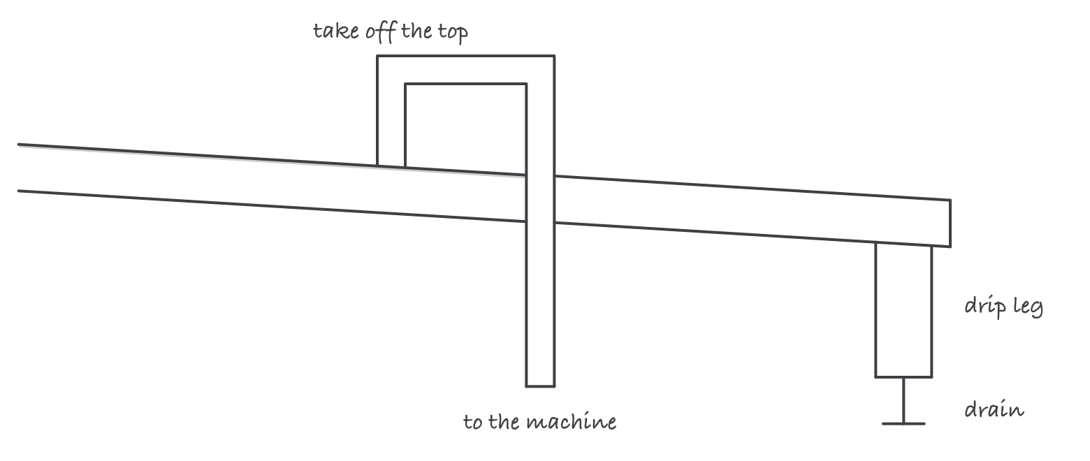
Water runs along the bottom of the pipe, so branches come off the top and the run ends in a drip leg you can drain
The FRL, and what each letter does
At the machine, air passes through an air preparation unit, commonly called an FRL.
- Filter removes particulate and bulk liquid water. Most have a bowl with a drain, and those drains are routinely neglected.
- Regulator drops header pressure to what the machine needs, and holds it steady as flow changes. The gauge on the regulator reads what the machine gets, not what the plant makes.
- Lubricator adds a controlled mist of oil for tools and cylinders that need it. Many modern components are pre-lubricated and are damaged by added oil, so a lubricator is fitted when the equipment calls for one, never as a default.
Where it bites
- Never use compressed air to blow off skin or clothing. Air can be forced into the bloodstream or into body cavities, and the injury is severe and immediate.
- A pneumatic system holds energy after shutdown. The receiver, the header, and every accumulated volume have to be bled and verified during energy control, not assumed to have leaked down.
- Speed control on air goes in the exhaust. Metering the air out gives smooth motion because the cylinder stays cushioned against a back pressure; metering it in gives the lurching, uneven stroke people call chatter.
- Leaks run 168 hours a week. A leak you can hear across a quiet shop is a running cost every hour of every shift, including the ones nobody is working.
- Undersized pipe shows up as pressure that sags under load. The gauge at the compressor reads fine while the machine at the end of a long small-bore run starves.
- Do not raise header pressure to fix a machine problem. It masks a restriction or a leak, raises every leak’s flow rate across the plant, and costs energy continuously.
Exam relevance
Expect the compression ratio and free-air conversion, scfm arithmetic, the FRL and what each element does, the reason drops come off the top of the header, and meter-out speed control. Expect a safety question on blowing off with compressed air and one on residual pressure during energy control. The NCCER Industrial Maintenance and Millwright programs both teach pneumatics beside hydraulics, and exam questions frequently ask you to say which of the two properties (compressibility or incompressibility) explains a stated behavior.