Learn · Industrial Maintenance
Hydraulic Components and Circuits
Part of Maintenance Tech to CMRP · step 12 of 30 · next: Pneumatics
In learning paths: Maintenance Tech to CMRP
Assumes you know: Hydraulics Fundamentals
A hydraulic circuit is four kinds of component and the lines between them: something to make flow, something to steer it, something to limit it, and something to turn it back into mechanical motion. Learn to sort every part you meet into one of those four boxes and a schematic stops being a wall of symbols.
Why it matters on the job
Nobody troubleshoots a hydraulic system by looking at it. The oil is opaque, the parts are steel, and the fault is usually a spool, a seal, or a spring you cannot see. The schematic is the only view you get, and reading it is a skill in the same category as reading a wiring diagram: slow at first, then the fastest tool you own.
Pumps make flow
A pump’s size is its displacement, the volume it moves per revolution, in cubic inches per revolution. Flow follows from displacement and speed, nothing else.
Fixed displacement pumps (gear, most vane designs) move the same volume every revolution. Flow the system does not need goes over the relief valve and becomes heat.
Variable displacement pumps (piston, some vane) change their own displacement while running. A pressure-compensated piston pump destrokes itself to near zero flow when the system reaches its set pressure, so it stops pumping oil it has nowhere to put. That is why variable pumps run cooler on systems that hold pressure without moving.
Volumetric efficiency is the gap between what a pump should deliver and what it does, and watching it fall over time is a useful predictive measure.
Worked example: sizing from the pump up
A pump of 1.50 in³/rev turns at 1,800 rpm.
Theoretical flow. 1.50 in³/rev × 1,800 rev/min = 2,700 in³/min, and 2,700 ÷ 231 = 11.69 gpm.
Actual flow. At 92% volumetric efficiency, 11.69 × 0.92 = 10.75 gpm. That is the number the actuators actually see.
Power draw. At a 2,000 psi working pressure, hydraulic power is 10.75 × 2,000 ÷ 1,714 = 12.54 hp. Allow 85% overall efficiency for the pump and drive and the prime mover has to supply 12.54 ÷ 0.85 = 14.76 hp, so this circuit gets a 15 hp motor.
Now watch the diagnostic value of the same arithmetic. If that pump measures 9.4 gpm at the same speed a year later, its volumetric efficiency has fallen to 9.4 ÷ 11.69 = 80%, and the missing 2.3 gpm is slipping internally and turning straight into heat. The pump has not failed. It is telling you, in a number, that it is going to.
Valves steer, limit, and meter
Three families, and every valve you meet is in one of them.
Directional control valves decide where the oil goes. A 4/3 valve has four ports (P from the pump, T to tank, A and B to the actuator) and three positions. On a schematic it is drawn as three boxes side by side, and the trick to reading it is this: the ports stay still and the boxes slide across behind them. Whichever box is lined up with the ports is the connection you have.
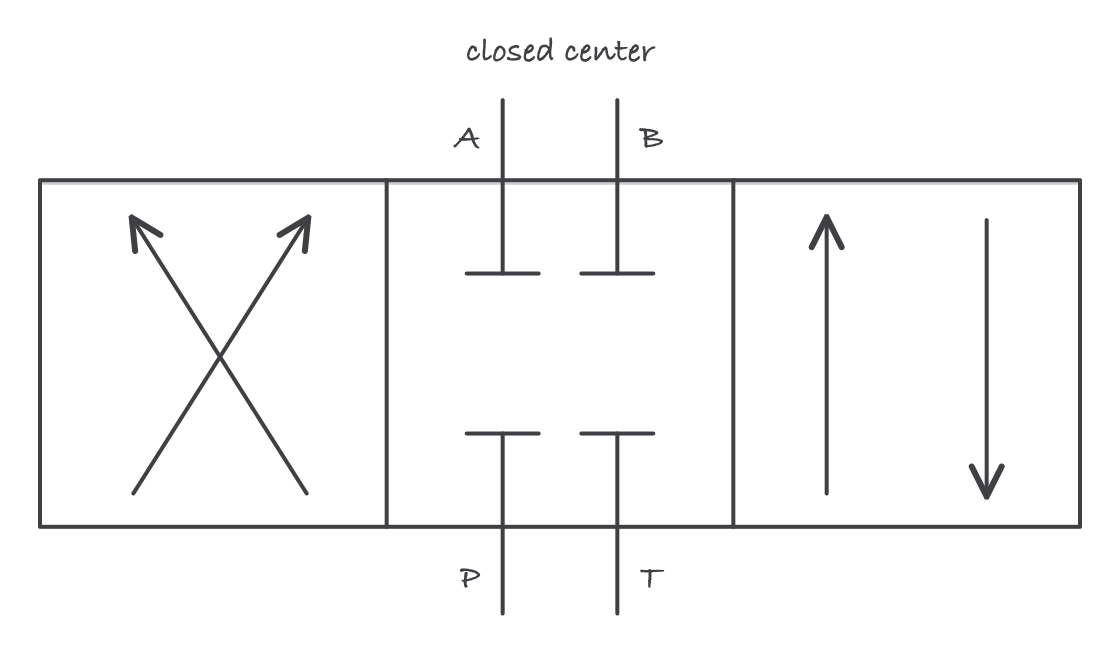
Read the symbol by sliding the boxes, not the ports: the box in front of the ports is the circuit you have right now
The center condition is the box in the middle, and it matters more than beginners expect.
- Closed center blocks all four ports. The actuator holds position, and pressure stays trapped between the valve and the cylinder. That trapped pressure is stored energy, and it has to be relieved during energy control.
- Tandem center blocks A and B but connects P to T, so the actuator holds while the pump unloads to tank at low pressure.
- Open center connects everything to tank. The actuator floats and the pump unloads.
- Float center blocks P while connecting A and B to tank, so the actuator can be moved by an outside force.
Pressure control valves limit or set pressure.
- A relief valve is the system’s protection: it opens to tank above its setting, and it is set for the weakest component in the circuit.
- A pressure reducing valve holds a lower pressure in one branch of a circuit that runs higher elsewhere.
- A sequence valve does not let a second actuator start until the first has reached a set pressure.
- A counterbalance valve holds a load against gravity, so a raised platen does not free-fall when the directional valve shifts.
Flow control valves set speed by restricting flow. A plain needle valve restricts by a fixed opening, so the flow it passes changes when pressure changes. A pressure-compensated flow control keeps the flow constant regardless of load, which is what you want when the actuator’s speed has to stay the same as its load varies. Meter-in control puts the restriction ahead of the actuator; meter-out puts it after and is the one that controls a load trying to run away.
Accumulators store energy
An accumulator is a vessel with gas on one side of a bladder, piston, or diaphragm and hydraulic oil on the other. Nitrogen precharge compresses as oil enters, and that compressed gas gives the oil back when the system asks for it.
They exist to supply short high-flow demands, to absorb shock and pressure spikes, and to hold pressure against leakage.
They also mean the system stays pressurized after the pump stops, which puts them squarely in the middle of energy control. An accumulator with a manual dump valve should have that valve in the lockout procedure, and it should be operated and verified, not assumed.
Reading a schematic
- Solid lines are working lines. Dashed lines are pilot lines. Dash-dot lines enclose an assembly that ships as one unit.
- A solid triangle in a symbol means hydraulic fluid; an open triangle means air. That one distinction tells you which system a shared drawing belongs to.
- Follow one path at a time. Pump to directional valve, valve to actuator, actuator back through the valve to tank. Every fault has to be somewhere on a path you can trace.
- Read what the circuit does with no one touching it. Solenoids de-energized, springs relaxed: that is the state the machine sits in overnight and the state you meet when you open the panel.
Where it bites
- A pressure gauge in the wrong place tells you very little. Reading at the pump outlet does not tell you what the cylinder sees if there is a restriction between them.
- Filters have a bypass. When a filter clogs, most designs open a bypass so the pump keeps flowing, which means unfiltered oil circulates while everything looks normal. The indicator on the filter head is the only warning you get.
- Nitrogen only. Precharging an accumulator with shop air or oxygen is a violent mistake. Check precharge on a system with the oil side vented, following the accumulator maker’s procedure.
- Do not adjust a compensator to chase a symptom. A destroking pump that will not build flow is usually a compensator setting someone else already chased.
- Meter-out is not optional on overrunning loads. A load that can pull the cylinder faster than the oil is fed cavitates the cylinder and slams at the end of stroke.
- Center condition decides your energy control steps. A closed-center machine still holds pressure after shutdown, and the procedure has to say how that pressure is relieved and verified.
Exam relevance
Expect to sort components into the four functions, to read a 4/3 valve symbol including its center condition, to name what each pressure-control valve does, and to compute pump flow from displacement and speed. The NCCER Industrial Maintenance and Millwright programs both build fluid power from components to circuits in this order. The question that separates candidates is the center-condition one, because it requires you to say what the machine is doing when nothing is energized.