Learn · Industrial Maintenance
VFDs in Maintenance
Part of Maintenance Tech to CMRP · step 21 of 30 · next: Preventive Maintenance
In learning paths: Maintenance Tech to CMRP
Assumes you know: Motor Control Circuits
A variable frequency drive takes the fixed 60 Hz supply, turns it into DC, and builds a new alternating supply at whatever frequency and voltage the motor needs. Since an induction motor’s speed follows the frequency it is fed, controlling frequency controls speed, and that one capability is why drives are now common on large fans and pumps in industry.
Why it matters on the job
A drive changes the maintenance problem in three directions at once. It saves large amounts of energy on centrifugal loads, introduces electrical stresses the motor was not originally designed for, and produces a fault log that tells you what happened if you know how to read it.
It also puts a capacitor bank between you and the machine. A drive holds a lethal charge on its DC bus after the supply is removed, which makes the drive a specific, named step in the machine’s energy control procedure rather than a box on the wall.
What is inside
Three stages, in order.
- Rectifier. Diodes (or controlled devices) turn the incoming three-phase AC into DC.
- DC bus. Capacitors smooth and store that DC. This is where the energy lives, and where it stays after you open the disconnect.
- Inverter. Fast switching transistors (IGBTs) chop the DC bus into pulses whose width varies, so the average over each cycle traces out a sine wave at the frequency you asked for. That is pulse width modulation, and the pulses are the source of most of the drive’s side effects.
Speed and volts per hertz
An induction motor’s synchronous speed is set by supply frequency and the number of poles:
synchronous speed (rpm) = 120 × frequency ÷ poles
Actual shaft speed is a little lower because an induction motor slips, but the frequency sets where it runs.
Now the part that decides whether the motor survives. The magnetic flux in a motor depends on the ratio of voltage to frequency, not on either one alone. Drop frequency at full voltage and the flux rises, the iron saturates, and current climbs. So the drive reduces voltage in step with frequency, holding the volts-per-hertz ratio constant, which keeps flux constant and makes full torque available all the way down.
Above base frequency the drive cannot raise voltage past what the supply gives, so V/Hz falls, flux falls, and available torque falls with it. That upper region is constant horsepower, not constant torque, and running a constant-torque load up there overloads the motor.
Worked example: a fan drive at 45 Hz
A 4-pole motor is rated 460 V at 60 Hz and drives a centrifugal fan that absorbs 25 hp at full speed. The drive is commanded to 45 Hz.
Synchronous speed at 60 Hz. 120 × 60 ÷ 4 = 1,800 rpm.
Volts per hertz. 460 V ÷ 60 Hz = 7.667 V/Hz.
At 45 Hz. Synchronous speed is 120 × 45 ÷ 4 = 1,350 rpm, and the drive supplies 7.667 × 45 = 345 V.
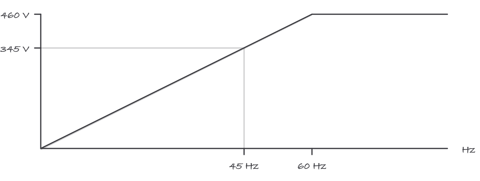
Voltage rises in step with frequency up to base speed, then stops, because there is no more voltage to give
What it saves. On a centrifugal load the affinity laws apply: flow varies with speed, pressure varies with speed squared, and shaft power varies with speed cubed.
Speed ratio = 45 ÷ 60 = 0.75.
Power ratio = 0.75³ = 0.4219.
Power = 25 hp × 0.4219 = 10.5 hp.
Read that result carefully, because it is the entire economic case for drives. Cutting to 75% of the air takes 42% of the power. The same 25% reduction achieved by closing a damper leaves the fan working near full load and throws the difference away as turbulence across the damper blades.
And note the trap in the same arithmetic. A 10% speed increase costs 1.10³ = 1.33, a 33% rise in shaft power, which is how a fan gets “sped up a little” straight into a motor overload.
Reading the fault log
Fault codes are the drive telling you which of its protections operated. The vocabulary is nearly universal even though the code numbers are not.
- Overcurrent. A mechanical problem far more often than an electrical one: a jam, a seized bearing, a load that changed, or acceleration set faster than the load can follow.
- Overvoltage. Usually deceleration too fast on a high-inertia load. The motor becomes a generator, pushes energy back into the DC bus, and the bus rises until the drive trips. Lengthen the decel ramp, or fit dynamic braking.
- Undervoltage. The supply sagged or was interrupted. Look upstream, not at the drive.
- Overtemperature. Blocked filters, a failed cooling fan, an enclosure with no ventilation, or an ambient the drive is not rated for.
- Ground fault. Insulation failure in the motor or the motor cable, and it usually means a megger test on both.
- Motor overload. The drive’s thermal model says the motor has been drawing too much for too long. Check the load and check that the drive’s motor parameters actually match the nameplate.
A drive that trips repeatedly on the same code is reporting a plant problem. Resetting it is the equivalent of resetting an overload relay without asking why.
What drives do to motors
- Shaft voltage and bearing currents. PWM switching produces a common-mode voltage that induces a voltage on the motor shaft. When it discharges through a bearing, it pits and eventually flutes the race, and the machine develops a bearing failure with no mechanical cause. The defenses are a shaft grounding ring, an insulated bearing at one end, and a proper high-frequency bonding path through shielded drive cable installed the way the drive manual specifies.
- Voltage stress at the motor terminals. Fast switching edges traveling down a long motor cable reflect at the motor and can add to the incoming pulse, so the motor sees peaks higher than the drive’s output. Long cable runs need a load reactor or a dV/dt filter, and the drive manual states the length at which it starts to matter.
- Cooling at low speed. A totally enclosed fan-cooled motor is cooled by a fan on its own shaft. Run it slowly on a constant-torque load and it makes near full current with a fraction of the airflow. Constant-torque applications at low speed need a motor rated for it or a separately powered blower.
- Inverter-duty motors exist because of the first two items: their insulation systems are built for the voltage stress a drive produces. Retrofitting a drive onto an old motor is a decision about insulation, not about horsepower.
Maintenance the drive actually needs
- Keep it cool and clean. Heat sinks, filters, and cooling fans. Drive failures often trace to temperature, and cooling fans are wear items with a finite life.
- Torque the power connections at the interval the manufacturer states. Loose lugs on a drive make heat exactly where you least want it.
- Save the parameter set. Print it, export it, and store it somewhere other than the drive. A replacement drive with default parameters does not run the machine.
- Read the fault history at every visit, not only after a trip. The log shows the near-misses.
- Reform the capacitors on a spare drive that has sat in stores for a long period, following the manufacturer’s procedure, before it goes into service.
Where it bites
- The DC bus stays live after the disconnect opens. Wait the manufacturer’s stated discharge time, then verify at the bus terminals with a meter rated for the job, under your plant’s electrical safety program. The charge indicator lamp going out is not verification.
- Do not open the motor disconnect while the drive is running. Interrupting the output of a running drive can damage the output stage. Stop the drive first, and use a drive-rated output disconnect with an auxiliary contact if the machine needs one.
- Do not put a power factor correction capacitor on a drive output. It is a fault waiting for a switching edge.
- Never megger a motor with the drive still connected. Disconnect the motor leads at the drive first, or you will put test voltage across the output transistors.
- A drive is a stored energy source in the LOTO procedure. Both the DC bus and the drive’s ability to restart on a command from elsewhere have to be addressed, and neither is handled by pressing stop.
- Bearing fluting looks like a mechanical failure and is not. A washboard pattern on a race, on a drive-fed motor, is an electrical finding, and replacing the bearing without addressing the current path buys you the same failure again.
Exam relevance
Expect the synchronous speed formula, the volts-per-hertz relationship and why it is held constant, the affinity-law cube relationship for centrifugal loads, and fault-code interpretation as a scenario. Expect a safety question on the DC bus after disconnection. The CMRT’s hands-on domains include drives as everyday plant equipment, and the NCCER Industrial Maintenance program places them alongside motor controls in its upper levels.
Verified requirements
| Where | Expires | Renewal | Continuing education |
|---|---|---|---|
| United States (federal) | Yes | 3 years | 50 course hours per 3-year cycle, drawn from two or more of the recertification activity categories; recertification application due within 90 days of the expiration date or the exam must be retaken |
Information comes from issuing-authority sources. Confirm current rules, fees and eligibility with the authority before acting.