Learn · Industrial Maintenance
PLC Fundamentals
Part of Maintenance Tech to CMRP · step 19 of 30 · next: Sensors and Instrumentation
In learning paths: Maintenance Tech to CMRP
Assumes you know: Motor Control Circuits
A programmable logic controller reads the state of every input, solves a program using that snapshot, writes the results to its outputs, and then does it all again. That repeating loop is the scan, and nearly everything that surprises people about PLCs comes from the fact that the machine works in these discrete passes rather than continuously.
Why it matters on the job
A PLC replaced a panel of relays, and it kept the relay panel’s language. If you can read a ladder rung on paper you can read one on a laptop, which means the step from motor control into PLC troubleshooting is smaller than it looks.
The payoff is large. A PLC will show you the live state of every input bit, every output bit, and every rung, which turns “the machine will not start” into a specific question about one bit. But that same visibility misleads people who do not know what the bit represents, and the misdiagnoses are expensive.
The scan
Every scan runs the same four stages.
- Input scan. The processor reads the physical state of every input point and stores it in the input image table. This is a snapshot, taken at one instant.
- Program scan. The processor solves the ladder logic from top to bottom, left to right, using the snapshot. Field devices changing during this stage are not seen.
- Output scan. The processor writes the output image table to the physical output modules. Only now do contactors, valves, and lights actually change.
- Housekeeping. Communications, diagnostics, and the watchdog check that the whole loop completed in time.
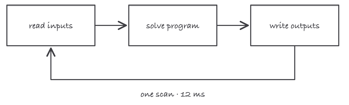
Inputs are read once per pass, the program runs on that snapshot, and outputs change only at the end of the pass
Two consequences follow, and both cause real faults.
Order matters within the program scan. An output written on rung 5 is seen as an input condition by rung 20 in the same scan, but a rung above it will not see the change until the next pass. Rung order is logic, not layout.
An event shorter than a scan can be missed entirely. If a proximity sensor is on for less time than one full scan takes, the input scan can happen before and after the pulse and never see it.
Worked example: will the PLC see the part?
A conveyor carries 1.00 in long parts past a proximity sensor. The PLC’s scan time is 12 ms.
At 200 ft/min. Belt speed is 200 ft/min × 12 in/ft = 2,400 in/min, which is 2,400 ÷ 60 = 40 in/s. A 1.00 in part is in front of the sensor for 1.00 ÷ 40 = 0.025 s = 25 ms. That is 25 ÷ 12 = 2.1 scans, so every part gets seen by at least two input scans. Reliable.
At 600 ft/min. Belt speed is 600 × 12 ÷ 60 = 120 in/s, and the part is present for 1.00 ÷ 120 = 0.00833 s = 8.3 ms. That is 8.3 ÷ 12 = 0.69 of a scan, so the pulse can start and finish entirely between two input scans. Parts will be missed, intermittently, in a way that looks like a failing sensor.
The fix is not a new sensor. Options that actually address it: latch the pulse in hardware or in a sensor with an output-extension setting, move the signal to a high-speed input or counter module that does not wait for the scan, or reduce scan time by simplifying the program.
Notice how the arithmetic reframes the complaint. “The sensor misses parts at high speed” became “the signal is present for 0.69 of a scan,” which is a solvable engineering statement rather than a parts-swapping exercise.
Inputs, outputs, and what a bit means
Discrete I/O is on or off: pushbuttons, limit switches, proximity sensors, contactor coils, pilot lights.
Analog I/O is a value: 4 to 20 mA, 0 to 10 V, a thermocouple or RTD input. The processor stores a number, and the scaling between that number and the engineering unit is set in software.
DC discrete inputs come in sinking and sourcing arrangements, which describe the direction of current flow between the field device and the module. Mixing them is a common wiring fault, and it produces a point that never turns on rather than an obvious error.
Now the concept that catches everyone. A ladder instruction drawn like a normally open contact does not describe a field device. It is an instruction that means examine this bit and pass power if it is 1. Whether that bit is 1 depends on how the field device is wired and what it is doing.
The practical consequence is the stop button. A stop button in the field is wired normally closed, so it holds its input bit at 1 while everything is fine, and the bit falls to 0 when the button is pressed or a wire breaks. In the program, that stop is therefore an examine-if-closed instruction, which reads backwards to anyone expecting the drawing to mirror the button. It is correct and deliberate: a broken wire and a pressed button do the same safe thing.
Troubleshooting with the program, not around it
There are only three places a discrete input path can fail, and they can be separated in under a minute.
- Is the field device doing its job? Meter or observe at the device.
- Is the module seeing it? The point’s status LED on the module.
- Is the bit in the image table set? Watch it online.
Compare them in that order.
- Device operating, module LED off: field wiring, a blown fuse, or a wrong sinking or sourcing arrangement.
- Module LED on, bit not set: an addressing error or a failed module.
- Bit set, rung not making: the logic is being blocked somewhere else, so read the rest of the rung.
- Output bit set, device not moving: the fault is on the output side, in the module, the wiring, or the load.
Where it bites
- Standard PLC logic is not a safety system. Emergency stops, safety gate interlocks, and guard monitoring belong in hardwired safety circuits or in safety-rated controllers, not in ordinary ladder logic. A processor fault must not be able to disable a stop function.
- A PLC does not replace lockout. The controller can turn an output on at any moment, including because someone edited a program from an office. Energy control isolates the power, not the logic.
- Forcing is not a diagnostic shortcut. A forced bit stays forced through mode changes and after you leave, and machines have started on forgotten forces. If you force anything, record it and remove it.
- Get the program backup before you change anything. The copy in the processor is the only copy in many plants, and the moment you need the original is after you have altered it.
- Rising scan time is a real symptom. A scan that has crept from 12 ms to 40 ms points at added logic, a communications problem, or a module fault, and it changes the timing behavior of everything the program does.
- An intermittent input is usually mechanical. Vibration on a limit switch, a loose ferrule, a chafed cable at a drag chain, a sensor set at the far edge of its range.
Exam relevance
Expect the four stages of the scan in order, the consequence that outputs update at the end of the scan, the difference between an instruction and a field device, and the sinking-versus-sourcing distinction. Expect the three-point troubleshooting comparison (device, module LED, image table bit) as a scenario question. The NCCER Industrial Maintenance program places PLCs in its upper levels, after motor controls, which is exactly the order in which the ideas make sense.