Learn · Industrial Maintenance
Motor Control Circuits
Part of Maintenance Tech to CMRP · step 18 of 30 · next: PLC Fundamentals
In learning paths: Maintenance Tech to CMRP
Assumes you know: Industrial Electrical for Mechanics
A motor control circuit is two circuits sharing an enclosure. The power circuit carries motor current at line voltage through the contactor’s main contacts. The control circuit carries a fraction of an amp at a lower voltage through pushbuttons, relay contacts, and a coil. Almost everything a maintenance technician does in a starter panel happens in the second one.
Why it matters on the job
The control circuit is where a machine’s logic lives in physical form, and it is readable. You can see the contacts, put a meter on them, and follow the path from supply to coil. That makes motor control the best place to learn systematic electrical troubleshooting, and it is why the skill transfers directly to reading a PLC program later.
It is also where a large share of plant downtime sits. A motor rarely stops because the motor failed. It stops because something in the control path opened.
Reading a ladder diagram
A ladder diagram is drawn between two vertical rails carrying the control supply. Each horizontal rung is one complete circuit path from one rail to the other.
The conventions are strict, and they carry meaning.
- Loads sit at the right end of the rung. A coil, a pilot light, a solenoid. One load per rung.
- Contacts sit to the left of the load, in the order the logic evaluates them.
- Contacts in series are AND. Every one must be closed for the rung to make.
- Contacts in parallel are OR. Any one closing is enough.
- Symbols show the de-energized, at-rest state. A contact drawn open is open when nothing is happening, whatever it does in service.
From those conventions comes the rule that organizes real panels: stop functions are normally closed devices wired in series, and start functions are normally open devices wired in parallel. Add a second stop button and it goes in series, so either one stops the machine. Add a second start button and it goes in parallel, so either one starts it.
The three-wire start/stop circuit
This is the circuit every plant runs, and it is worth knowing line by line.
From one rail: through a normally closed stop button, through a normally open start button, through the normally closed contact of the overload relay, into the contactor coil, and back to the other rail.
Press start and the coil energizes. The contactor pulls in, its main contacts close, and the motor runs. One more thing happens at the same time: an auxiliary normally open contact on the same contactor closes, and that contact is wired in parallel with the start button.
That parallel contact is the seal-in (also called the holding contact), and it is the whole trick. When you release the start button, current keeps reaching the coil through the seal-in. The circuit holds itself in.
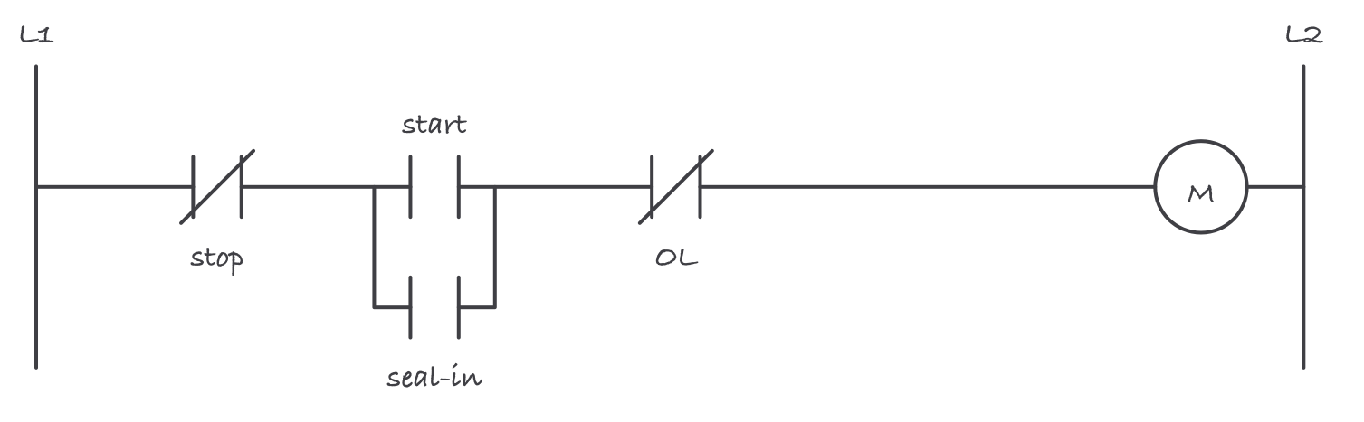
The seal-in contact closes when the coil pulls in, so the circuit keeps feeding itself once the start button is released
Press stop and the series path opens, the coil drops out, and the seal-in contact opens with it. The circuit cannot restart itself when you release the stop button. That is the definition of three-wire control, and its safety property is the one that matters: after a power failure, the motor stays off until somebody presses start.
Compare two-wire control, where a maintained device (a pressure switch, a float switch, a selector left in the run position) sits in place of the start button with no seal-in. The circuit follows the device. When power returns, the machine restarts by itself. That is correct for a sump pump and dangerous for a conveyor somebody may be standing on, and choosing between the two is a real decision rather than a wiring preference.
Overload protection is not short-circuit protection
Two different devices protect a motor circuit, and they are frequently confused.
Short-circuit and ground-fault protection (the fuses or the circuit breaker) acts in milliseconds against fault currents many times full load.
Overload protection (the overload relay) acts slowly against currents modestly above full load, because that is what a mechanically overloaded motor draws, and it is heat over minutes that kills the winding. The relay’s job is to model the motor’s heating and open before the insulation cooks.
The overload relay’s contact is in the control circuit, not the power circuit. It does not interrupt motor current. It drops the coil, and the contactor interrupts the motor current.
Set the overload to the motor’s nameplate full-load amps, adjusted for service factor as the manufacturer’s instructions direct. An overload set high because it “kept tripping” is a fault report someone wrote over.
Reversing, interlocking, and why both kinds exist
A reversing starter is two contactors feeding the same motor with two phases swapped. If both close at once, two phases are shorted line to line.
So a reversing starter carries two independent protections.
- Electrical interlocking: each contactor’s normally closed auxiliary contact is wired in series with the other’s coil, so energizing one prevents the other.
- Mechanical interlocking: a physical linkage between the two contactors that will not let both armatures pull in.
Both, always. Electrical interlocking fails if a contact welds; mechanical interlocking fails if the linkage is damaged or the contactors were replaced with unlinked units.
Worked example: tracing a dead control circuit
A conveyor will not start. Control voltage is 120 V, the circuit is the three-wire start/stop above, and the machine is otherwise safe to test under your plant’s electrical safety program.
Put one meter lead on the rail the coil returns to and leave it there. Then work along the rung with the other lead, holding the start button.
| Test point | Reading | Meaning |
|---|---|---|
| Supply rail | 120 V | Control power is present |
| Load side of stop button | 120 V | Stop button is closed and good |
| Load side of start button | 120 V | Start contact is making while pressed |
| Load side of overload contact | 0 V | The path opened here |
| Coil terminal | 0 V | Consistent with the above |
The voltage disappears across the overload contact, so that contact is open. Confirm it from the other direction by putting the meter across the overload contact: an open device in a series circuit carrying no current shows the full supply across it, so you should read 120 V there, while every closed device in the same rung reads close to 0 V.
Now go find out why. An overload relay opens because the motor drew too much current for too long, and that is a mechanical report as much as an electrical one: a seized bearing, a jammed conveyor, a wrong belt tension, a load somebody added. Resetting it without answering that question means resetting it again tomorrow, and eventually not in time.
Where it bites
- Symbols show the resting state, not the running state. A normally closed contact drawn closed may sit open all day on a running machine.
- A coil that hums or chatters is a supply problem more often than a coil problem. Low control voltage, a sagging control transformer, or a contact making poorly on the way in.
- Welded contacts do not open when the coil drops. A contactor whose main contacts have welded leaves the motor running with the coil de-energized, which is why energy control isolates at the disconnect and never at the start/stop station.
- Start/stop buttons are not an energy control device. Pressing stop is not isolation, and a machine that is stopped is not a machine that is locked out.
- Do not jumper around a device to see if that fixes it. Every jumper is a defeated protection until it is removed, and jumpers get left in.
- Wire numbers are the fastest tool in the panel. Terminals, wires, and the drawing share numbers, and using them turns a maze into a list.
Exam relevance
Expect to draw or read a three-wire start/stop rung and to identify the seal-in contact and what it does. Expect the two-wire versus three-wire question in the form of what happens after a power failure. Expect the overload-versus-short-circuit distinction, the series-stops and parallel-starts rule, and a rung-tracing question with meter readings. The NCCER Industrial Maintenance program builds motor controls in its upper levels, and the CMRT treats control troubleshooting as a technician competence.
Verified requirements
| Where | Expires | Renewal | Continuing education |
|---|---|---|---|
| United States (federal) | Yes | 3 years | 50 course hours per 3-year cycle, drawn from two or more of the recertification activity categories; recertification application due within 90 days of the expiration date or the exam must be retaken |
Information comes from issuing-authority sources. Confirm current rules, fees and eligibility with the authority before acting.