Learn · Solar
Racking and Mounting
Part of NABCEP PV Associate Prep · step 9 of 21 · next: Roof Attachments and Waterproofing
In learning paths: NABCEP PV Associate Prep
Assumes you know: PV System Components
Racking is the structure that carries an array’s loads into the building frame or the ground: rails, clamps, and attachments engineered as a system. It is the least glamorous layer of a PV install and the one that decides whether the array is still where you left it after ten years of wind, snow, and thermal cycling.
Why it matters on the job
Installers spend more hours on racking than on any other component, and it is the layer inspectors can actually see. Wrong attachment spacing, missed rafters, and under-torqued clamps are the classic first-year failures. They are also entirely preventable: every answer is printed in the racking manufacturer’s installation manual and the project’s engineering.
The load path
Every force on the array has to travel a continuous path: module, clamp, rail, attachment, structure. Three loads matter:
- Dead load is the constant weight of modules and hardware pressing down.
- Wind load pushes down on the windward slope and, worse, lifts up at edges and corners. Uplift, not weight, usually governs attachment spacing.
- Snow load adds seasonal weight where climate requires it.
The racking manufacturer publishes span and spacing tables for combinations of wind speed, snow load, and roof zone. Those tables, or a project-specific engineering letter, are the authority. Field judgment does not override them.
Mounting styles: pitched-roof arrays sit on rails (or rail-less attachments) parallel to the roof plane. Flat roofs typically use tilted or ballasted racking, where weight rather than penetration resists wind. Ground mounts carry the array on driven or concrete-set posts, trading roof work for foundations.
Worked example
One row of 8 modules, each 3.5 ft wide and 45 lb, mounts on two rails. Attachments are specified at 4 ft on center.
- Rail length: 8 × 3.5 ft = 28 ft
- Attachments per rail: 28 ÷ 4 = 7 spans, so 8 attachments (one at each end)
- Total for the row: 2 rails × 8 = 16 attachments
- Dead load per attachment: (8 × 45 lb) ÷ 16 = 360 ÷ 16 = 22.5 lb
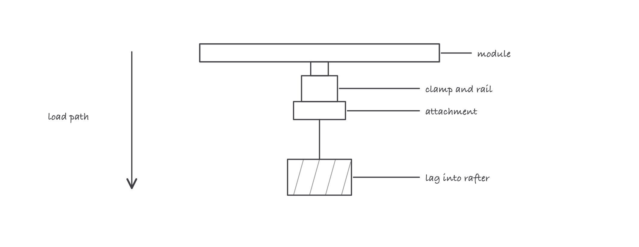
Every pound on the array travels module to clamp to rail to attachment to rafter: one missed rafter breaks the chain
The 22.5 lb of dead weight per attachment looks trivial, and it is. The spacing was never about weight: a design wind event pulls up on those same attachments with forces many times the dead load, which is why the 4 ft number comes from the manufacturer’s wind tables and not from a judgment call.
Where it bites
- Torque specs are part of the listing. Racking and module clamps are tested and listed as a system, at specified torques, often with a specific module frame. Swapping components or guessing torque voids the engineering. Use a torque wrench and the manual’s numbers.
- An attachment in sheathing is a failure waiting for wind. Lags must hit structure (rafter or truss) with the embedment the manual requires. Find the member, verify with a pilot hole, and relocate rather than hope.
- Thermal movement is real. Rails grow and shrink with temperature, and long runs need the expansion joints the manual specifies, or the array works its fasteners loose season by season.
- Roof work triggers fall protection. OSHA’s construction trigger is 6 feet above a lower level: racking work on nearly any roof qualifies. The safety lessons cover the systems; the rule applies from the first attachment.