Learn · Sheet Metal
Balancing Procedures
Part of Sheet Metal to TAB Certified · step 14 of 23 · next: TAB Certification (TABB, NEBB, AABC)
In learning paths: Sheet Metal to TAB Certified
Assumes you know: Airflow Measurement Instruments
Balancing is proportional. You do not walk a building setting each terminal to its design flow one at a time, because a duct system is interactive: every damper you close pushes air into every other path, undoing the terminal you set ten minutes ago. Instead you bring every terminal to the same fraction of its design flow, and only then raise the whole system together.
Why it matters on the job
Terminal-by-terminal balancing is the classic beginner’s day: eight hours of work, a system that is no more balanced than when you started, and dampers throttled so hard the fan is fighting the ductwork for the rest of the building’s life. The proportional method finishes in one pass, leaves the most restricted path wide open, and costs the owner the least fan energy that the installed system allows.
The sequence
1. Prepare, and do not skip this. Filters clean and in place, access doors closed, terminals installed, coils and controls set to the operating mode you are balancing in, fan rotation correct, belts and drives right. A system that changes underneath you cannot be balanced, and most “impossible” balances turn out to be a preparation item.
2. Take the totals first. Traverse the main duct and read the fan. You need to know what the system is actually moving before you touch a single damper, and the total tells you immediately whether you have a distribution problem, a capacity problem or both.
3. Find the index run. In each branch, read every terminal and divide the measurement by that terminal’s design flow. The terminal with the lowest ratio is the index: the most restricted path in that branch. Its damper stays wide open. There is nothing to gain by throttling the path that is already starving.
4. Proportion to the index. Trim the other terminals down toward the index terminal’s ratio. As you close dampers, air is pushed back into the open paths, so the readings climb while you work. Re-read and converge rather than setting a damper once and moving on.
5. Proportion the branches to each other, using the same logic one level up: find the branch running at the lowest ratio, leave its balancing damper open, and trim the others to match.
6. Set the fan last. With everything proportioned, one change at the fan raises the whole system in step until the index terminal reaches design and, because everything is proportional, so does everything else.
7. Re-read and record. Final measurements, final settings, marked dampers, and the report.
The fan laws, and why step 6 is not free
When the system curve is fixed (which it is, once the dampers stop moving), a change in fan speed moves three things at once:
- Airflow changes in direct proportion to speed.
- Static pressure changes with the square of speed.
- Brake horsepower changes with the cube of speed.
That cube is the one that ends days. A modest airflow increase asks for a much larger increase in shaft power, and the motor either has it or it does not.
Worked example: balancing a four-terminal branch
Four terminals, each designed for 1,000 CFM, so the branch design total is 4,000 CFM. Your first readings, dampers as installed:
| Terminal | Measured | Ratio |
|---|---|---|
| 1 | 950 CFM | 0.95 |
| 2 | 800 CFM | 0.80 |
| 3 | 1,100 CFM | 1.10 |
| 4 | 900 CFM | 0.90 |
Total measured: 950 + 800 + 1,100 + 900 = 3,750 CFM, against 4,000 design.
The index is terminal 2 at 0.80, the lowest ratio. Its damper stays open.
Proportion the other three down to 0.80, converging as the readings shift, until every terminal reads 0.80 × 1,000 = 800 CFM. The branch now moves 4 × 800 = 3,200 CFM, and every space is short by the same fraction. That is the point: a uniformly short system is one adjustment away from correct, while a randomly wrong one is not.
Now the fan. You need 4,000 CFM from 3,200, so the multiplier is 4,000 / 3,200 = 1.25.
- Speed: up 1.25, so a 25 percent increase in fan RPM.
- Static pressure: 1.25² = 1.5625, so system static rises about 56 percent.
- Brake horsepower: 1.25³ = 1.953, so the shaft power required nearly doubles.
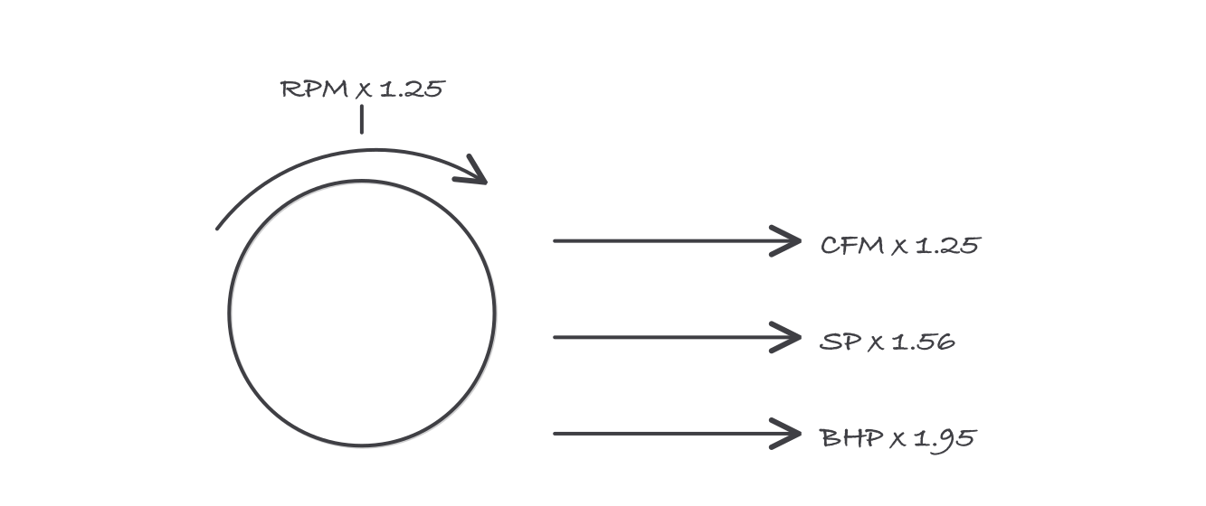
A 25 percent speed increase costs 95 percent more shaft power
Check the motor nameplate and the measured amps against that 1.95 before you change a sheave. A 25 percent airflow gain that overloads the motor is not a gain, and the honest finding is that the fan or the motor was undersized for the installed system.
The water side
Air is half the discipline. AABC requires its technicians to be competent in both air and water balancing, and hydronic balancing follows the same proportional logic with different instruments: flow measuring stations and balancing valves in place of pitot traverses and volume dampers, and pump laws in place of fan laws. A TAB technician who only does air is doing half the job the certification describes.
The report is the deliverable
Everything above produces a document, and the document has a review structure. TABB’s quality assurance program describes reports prepared by a technician and reviewed by a supervisor. NEBB states that only NEBB Certified Professionals working for certified firms may authenticate official reports. At AABC, the Test and Balance Engineer certifies the reports and supervises the technicians. Different titles, one idea: the person who took the readings is not the person who signs for them.
Where it bites
- Throttling the index run wastes energy and fixes nothing. If the most restricted terminal is closed down too, you have added resistance to a path that was already the bottleneck.
- Balance in the operating mode. A variable air volume system balanced with boxes in an artificial position is balanced for a condition the building never sees.
- Mark and lock what you set. An unmarked damper is a setting somebody will move, and a report describing settings that no longer exist is worse than no report.
- A terminal that will not reach design with its damper wide open is not a balancing problem. It is a design or an installation problem, and the report should say so rather than absorbing it silently.
- Volume dampers only. Fire dampers, smoke dampers and combination units are life-safety devices with their own inspection regime, and adjusting one is outside a TAB scope.
Exam relevance
Fan and pump laws are named explicitly in AABC’s published written exam content, which tells you how central they are to this part of the discipline. Expect proportional method questions that hand you a set of ratios and ask which terminal is the index, and fan-law questions that punish anyone who scales power linearly. Requirements and exam content are set by each certifying body, so confirm the current scope at the source.