Learn · Sheet Metal
Running a Duct Leakage Test
Part of Sheet Metal to TAB Certified · step 11 of 23 · next: TAB Fundamentals
In learning paths: Sheet Metal to TAB Certified
Assumes you know: Duct Sealing and Leakage Testing, Pressure Class, Seal Class and Leakage Class
A duct leakage test seals off a section of duct, pushes it up to a stated test pressure with a small fan, and measures the airflow needed to hold that pressure there. Whatever flow it takes to keep the pressure steady is the leakage, because in a perfectly tight section the answer would be zero. The rest of the procedure exists to make that one measurement trustworthy and repeatable.
Why it matters on the job
Two reasons, and only one of them is the contract.
The contract reason is that a leakage requirement is a performance requirement, so somebody has to prove the number. The better reason is diagnostic: a test that fails tells you the system leaks, and a test run section by section tells you where. Testing early, in sections, before the ceiling closes, is cheap. Testing the whole system after the building is finished is how a small leak becomes a demolition job.
The governing document
SMACNA publishes this as its own American National Standard, the HVAC Air Duct Leakage Test Manual (ANSI/SMACNA 016-2012). It covers the leakage criteria, the test procedures, the apparatus, the test setup and a sample leakage analysis, plus updates to the expected leakage rates for duct constructed to the HVAC Duct Construction Standards (Metal and Flexible).
That is the document to have open. The allowable rates, the test pressures and the setup details all come out of it for the class your specification named, and none of them should be carried in from another job.
The apparatus
Four things make up a leakage test rig, and each one answers a specific question.
A test fan supplies the air. It only has to replace what is escaping, so it is a small blower rather than the system fan.
A flow-measuring device in the line from the fan tells you how much air the fan is delivering. That reading is the leakage. This is the whole measurement, and it is why the fan cannot be a bare shop blower with no meter on it.
A manometer tapped into the duct reads the static pressure inside it. You bring the section to the specified test pressure and hold it there while the flow is read.
Caps and seals close every opening in the section: open ends, branch takeoffs, and any device connection that is not part of what you are testing. Every unsealed opening you leave is leakage you will measure and be blamed for.
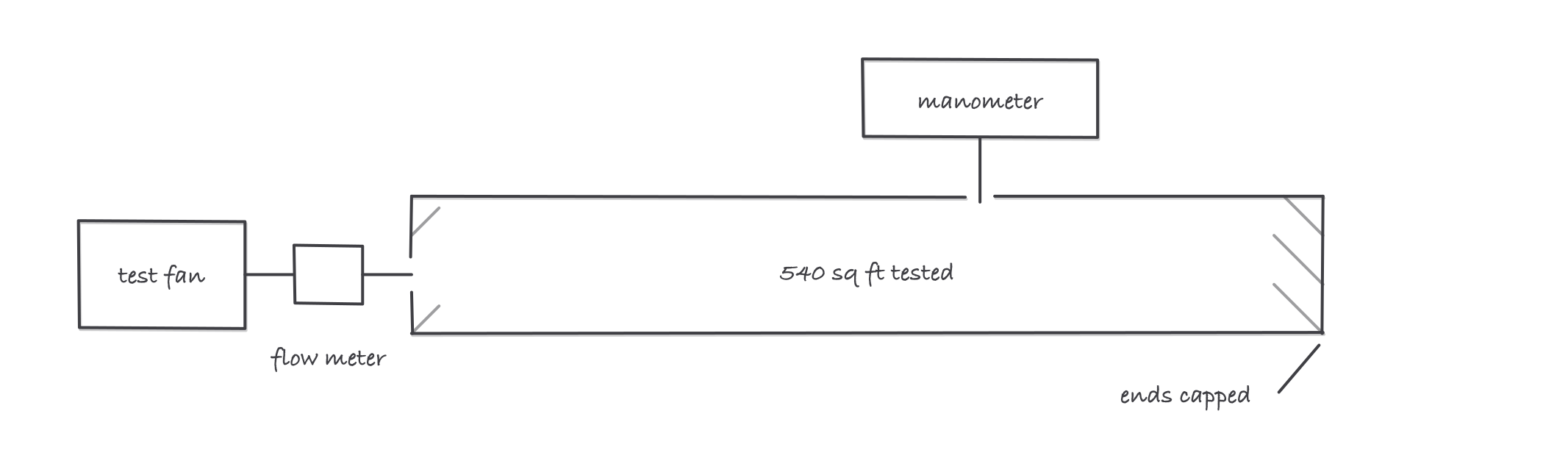
The measurement in one picture: the flow it takes to hold the test pressure is the leakage
Running the test
- Define the section and compute its surface area. Allowances are written against duct surface area, so the area is part of the result and not an afterthought.
- Cap it. Every opening. Then walk it again, because the one you missed is the one that changes the answer.
- Connect the fan through the flow meter, and tap the manometer into the duct. Tap somewhere representative, away from the fan connection where the local pressure is disturbed.
- Bring the section to the specified test pressure and let it stabilize. A reading taken while pressure is still rising is not a reading.
- Record the flow at that pressure. That flow is the leakage.
- Normalize it to surface area and compare it to the allowance for the specified class at that test pressure.
- If it fails, find the leaks and retest. Soap solution, a hand at the seams, or listening at a joint all work, and the failure is usually a small number of specific joints rather than a general condition.
Worked example
A test section is 60 ft of 36 in by 18 in rectangular duct.
Perimeter = 2 × (36 + 18) = 108 in, and 108 / 12 = 9 ft. Surface area = 9 ft × 60 ft = 540 sq ft.
The section is brought to the specified test pressure and the flow meter reads a steady 22 cfm.
Leakage per 100 sq ft = 22 / (540 / 100) = 22 / 5.4 = 4.07 cfm per 100 sq ft.
That 4.07 is the number you compare with the allowance for the specified leakage class at that test pressure, read out of the leakage manual.
Now see what the normalization does. Suppose the identical duct had been tested as a 30 ft section instead, with the leaks distributed evenly. Surface area would be 9 ft × 30 ft = 270 sq ft, the measured flow would be about half at 11 cfm, and 11 / 2.7 = 4.07 cfm per 100 sq ft again. Same duct, same verdict, different section length. That is the point of expressing leakage per unit area, and it is why arguing about section length is not a way out of a failed test.
This is not a blower-door test
Duct leakage testing pressurizes the ductwork and measures what escapes from the duct. Building envelope testing, the blower door, pressurizes the building and measures what escapes through the envelope. Different apparatus, different standards, different scope of work.
The industry keeps them separate too. ICB lists a Duct Air Leakage Testing Technician and a Building Envelope Installer Technician as separate certifications, and NEBB runs Building Enclosure Testing as a discipline of its own. When a client says “we need a leakage test,” establish which one they mean before you load the truck.
Where it bites
- An unsealed opening is measured as leakage. A failed test is often a capping failure rather than a construction failure. Count your caps against the drawing.
- Pressure must be stable before the flow is read. Flow and pressure move together while the section is filling, so an early reading overstates the leakage.
- The test pressure is a static pressure. It is what the manometer reads against the duct wall, and it is not the fan’s total pressure.
- Surface area is calculated, not estimated. Two runs of the same linear footage have different surface areas if their sizes differ, and the allowance follows the area.
- Flexible connections and devices are usually excluded. Test what the specification says to test. Including components that were never in scope produces a failure that is nobody’s fault and everybody’s argument.