Learn · Fire Protection
Hydraulic Calculations
Part of Sprinkler Fitter to NICET · step 4 of 21 · next: Standpipes and Fire Pumps
In learning paths: Sprinkler Fitter to NICET
Assumes you know: Sprinkler Heads and Response
A hydraulic calculation proves, number by number, that the water supply can push enough water through the actual pipe network to the sprinklers that need it. The method has three moving parts: a design density applied over a remote area, the head flow equation Q = K√P, and a node-to-node march from the most remote head back to the supply, adding friction and elevation losses as you go.
Why it matters on the job
Hydraulic calculation is the line between fitting pipe and laying out systems. It is the core technical skill of the sprinkler designer, the reason a system’s pipe sizes are what they are, and the subject NICET dedicates an entire Layout Level III exam to. When a fitter asks “why is this main 4 inch here and 2½ inch there,” the calc is the answer.
Density and the remote area
The design criteria give you two numbers: a density (gpm per square foot of floor) and a design area (the hydraulically most demanding remote area, in square feet). The claim being proven is: if a fire opens every head in that worst-case area, each one still gets at least its share of water. You do not multiply density by the whole building. You prove the hardest patch, and everything nearer the supply is then easier by construction.
Each head’s minimum flow is density times the floor area that head covers.
The chain: work back toward the supply
Start at the most remote head and walk toward the source, one node at a time:
- Set the end head’s flow and pressure (from density, coverage and Q = K√P, respecting any minimum head pressure the criteria impose).
- Add friction loss along the pipe to the next node (from Hazen-Williams tables: loss depends on flow, pipe size and pipe roughness), plus elevation change at 0.433 psi per foot of height.
- The next head sees that higher pressure, so by Q = K√P it must flow more. Add its flow to the total and keep walking.
The output at the source is a demand point: total gpm at total psi, and the water supply curve must clear it.
Worked example: two heads on a branch
Design criteria for the job: 0.10 gpm/ft² density, heads covering 130 ft² each, K = 5.6 heads, minimum 7 psi at any flowing head.
Head 1 (most remote). Required flow: 0.10 × 130 = 13.0 gpm. Pressure to produce it: P = (Q/K)² = (13.0/5.6)² = (2.321)² = 5.39 psi. That is below the 7 psi floor, so the floor governs: P₁ = 7 psi, and the head actually flows Q₁ = 5.6 × √7 = 5.6 × 2.6458 = 14.8 gpm.
Pipe to head 2. 12 ft of branch line whose friction table gives 0.11 psi/ft at this flow: loss = 12 × 0.11 = 1.32 psi. No elevation change on a level branch. So P₂ = 7 + 1.32 = 8.32 psi.
Head 2. It sees more pressure, so it flows more: Q₂ = 5.6 × √8.32 = 5.6 × 2.8844 = 16.2 gpm.
Running demand after two heads: 14.8 + 16.2 = 31.0 gpm, and the friction for the next stretch of pipe is computed at 31.0 gpm, not 14.8. That compounding is the whole character of the calc: flows grow toward the supply, and friction grows with the square-ish power of flow.
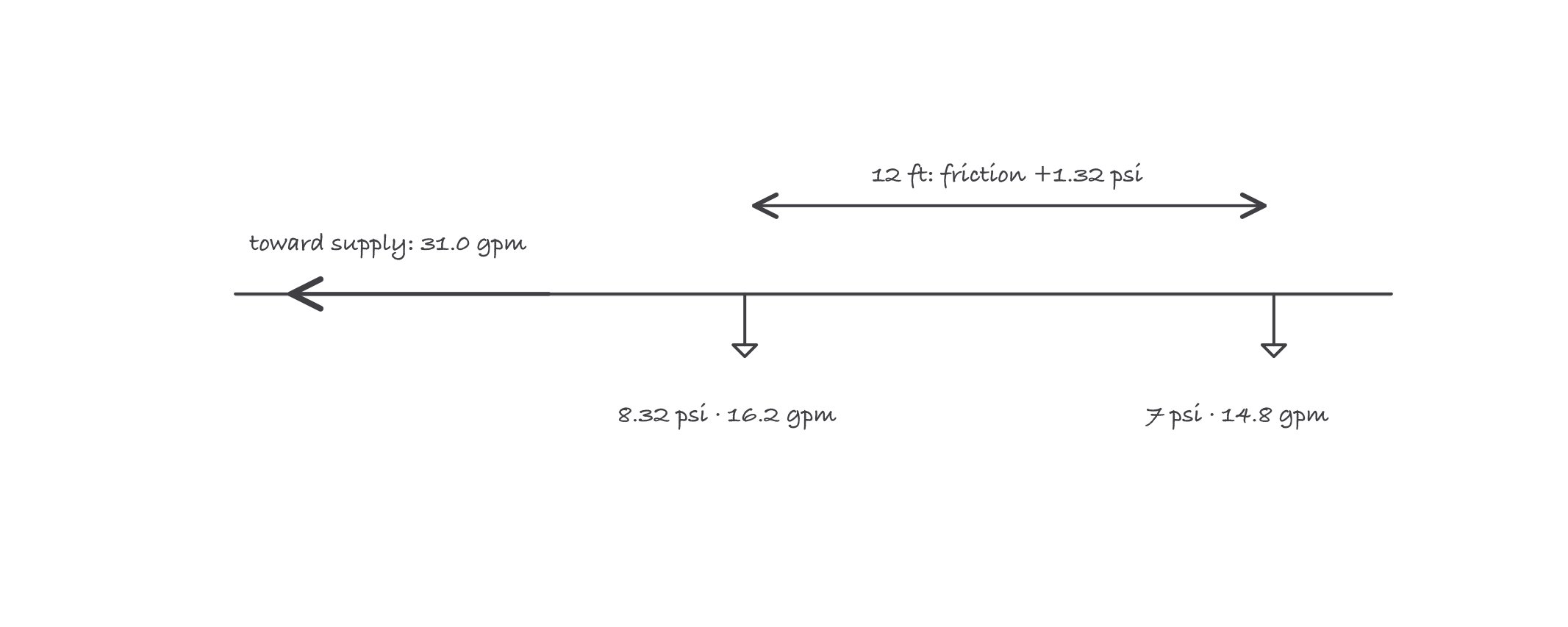
The march to the source: every node closer to the supply sees more pressure, so every head flows more than the last
Where it bites
- Heads nearer the supply always over-discharge. Learners expect every head to flow the minimum. Only the end head does; the rest flow whatever their local pressure forces through Q = K√P. Total demand is always more than density times area.
- The minimum-pressure floor can govern. As in the example: the density math wanted 5.39 psi, the criteria demanded 7. Always check both and take the larger.
- Friction tables are per flow, size and C-factor. Reusing a friction value after the flow has grown is the classic chain-breaking error. Recompute at every segment.
- Elevation is not friction. 0.433 psi per vertical foot appears and disappears with height changes regardless of flow. Keep the two loss columns separate or the calc cannot be checked.
Exam relevance
Hydraulics is where NICET’s Water-Based Systems Layout track gets serious: Level III includes a dedicated hydraulic calculation exam (60 questions, 240 minutes, at Pearson VUE). Expect to produce exactly this chain by hand: density to end-head flow, Q = K√P in both directions, segment-by-segment friction and elevation, and a supply-versus-demand verdict. Drill the two-head example until you can extend it to a full branch without notes.
Verified requirements
| Where | Expires | Renewal | Continuing education |
|---|---|---|---|
| United States (federal) | Yes | 3 years | CPD required each 3-year certification period |
Information comes from issuing-authority sources. Confirm current rules, fees and eligibility with the authority before acting.