Learn · Low Voltage and Telecom
Initiating Devices and Notification Appliances
Part of Fire Alarm Technician, NICET Track · step 2 of 11 · next: Fire Alarm Circuits (NAC, SLC, IDC)
In learning paths: Fire Alarm Technician, NICET Track
Assumes you know: Fire Alarm System Fundamentals
Initiating devices are the fire alarm system’s senses; notification appliances are its voice. Everything on an initiating circuit exists to detect (smoke, heat, a human pulling a lever, water flowing in a sprinkler pipe), and everything on a notification circuit exists to make occupants leave (horns, strobes, speakers). NFPA 72 dedicates a chapter to each: initiating devices and their placement in Chapter 17, notification appliances and their coverage in Chapter 18.
Why it matters on the job
Device selection and placement is where fire alarm design meets the physical building, and it is the part inspectors walk with drawings in hand. Put a smoke detector in a dusty shop and you have designed a false alarm generator. Space detectors too far apart and you have designed a blind spot. Both errors are invisible on the panel and obvious on the ceiling.
Initiating devices
- Manual pull stations: the human input, mounted along exit paths so anyone can raise the alarm on the way out.
- Smoke detectors: photoelectric types sense light scattered by smoke particles in a chamber; ionization types sense the current change smoke causes in an ionized gap. Photoelectric dominates modern commercial work.
- Heat detectors: fixed-temperature units operate at a set point; rate-of-rise units respond to fast temperature climbs. Heat is the choice where smoke detection would false: kitchens, garages, dusty or steamy spaces.
- Sprinkler monitoring: a waterflow switch reports water moving in the sprinkler system, and it initiates an alarm. A valve tamper switch reports someone closing a sprinkler valve, and it initiates a supervisory signal, not an alarm. That pairing is a fixture of exams and of real panels.
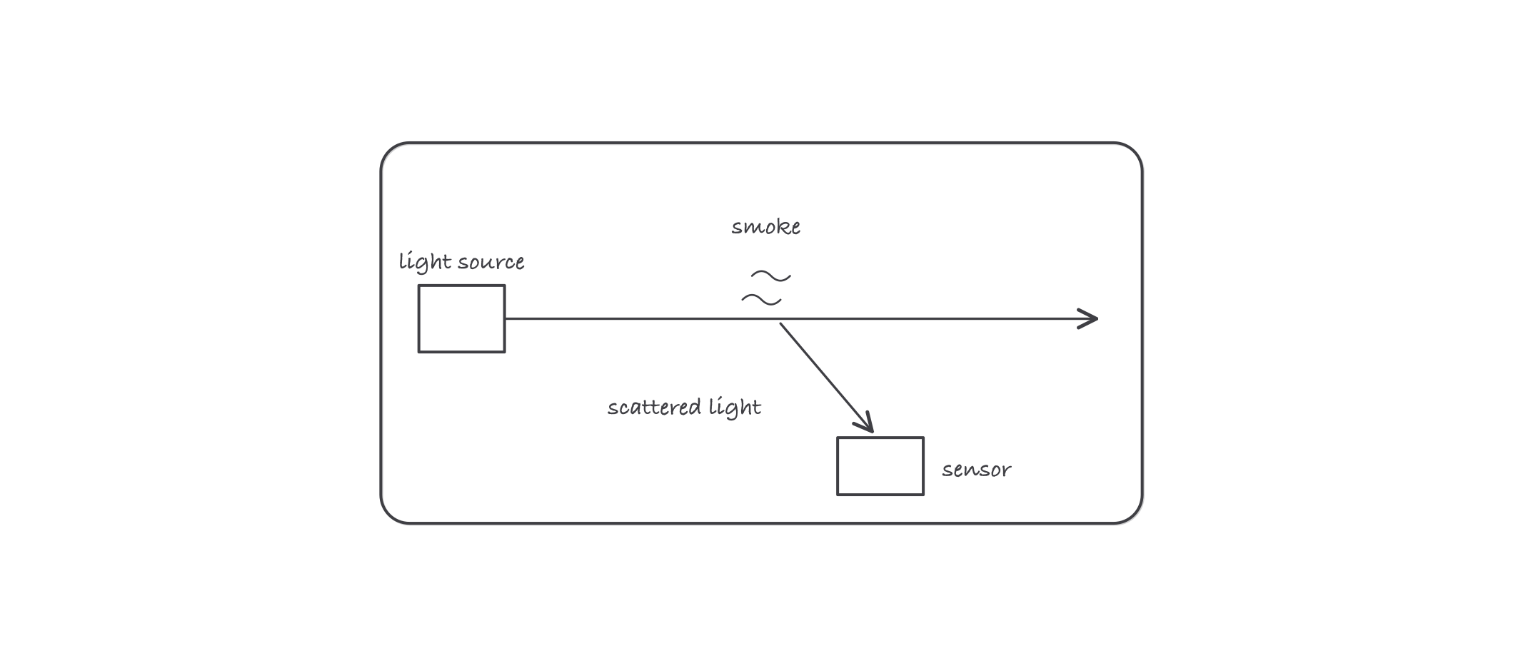
Clean air lets the beam pass unseen; smoke scatters light onto the sensor and the detector trips
Notification appliances
Horns and speakers carry the audible signal; strobes carry the visual one so that occupants who cannot hear the alarm still receive it. Audible coverage is specified above the ambient sound level of the space, and strobe coverage is specified by intensity (candela ratings) and placement rules per Chapter 18. The design goal is blunt: every occupiable space gets the message.
Worked example: spacing spot detectors
A smooth-ceiling corridor is 30.5 m (100 ft) long. The spot smoke detectors are applied at a listed spacing of 9.1 m (30 ft): the classic smooth-ceiling layout rule puts detectors no more than one full spacing apart, and no more than half a spacing (4.6 m) from each end wall.
- Minimum count: 30.5 ÷ 9.1 = 3.35, so 3 detectors cannot cover the corridor; use 4.
- Even layout: divide the corridor into 4 equal coverage lengths of 30.5 ÷ 4 = 7.6 m, and center a detector in each: positions 3.8 m, 11.4 m, 19.1 m, 26.7 m from one end.
- Check: gaps between detectors are 7.6 m ≤ 9.1 m, and each end wall is 3.8 m ≤ 4.6 m from its nearest detector. The layout complies.
The general rule to carry: divide, place, then verify both the between-device gaps and the end-wall distances.
Where it bites
- Waterflow is alarm; tamper is supervisory. Wiring or programming them alike is a code violation and a dangerous one: a closed valve silently disables sprinkler protection.
- Detector choice is about the environment, not the catalog. Every nuisance-alarm complaint traces to a detector asked to work somewhere its sensing physics cannot tolerate.
- Strobes are engineering. Candela rating and placement come from coverage requirements. Swapping in a different rating “because it fits” changes the design.
- Household smoke alarms are not system detectors. A smoke alarm (the residential unit with the built-in sounder) and a system smoke detector answer to different rules and different chapters.