Learn · Low Voltage and Telecom
Fiber Optics: Types, Splicing, Testing
Assumes you know: Structured Cabling Overview
Fiber optic cable carries data as light through a glass core thinner than a hair, and one distinction organizes everything else: singlemode fiber has a core about 9 µm across and carries one path of laser light for kilometers; multimode fiber has a larger core, commonly 50 µm, that carries many overlapping light paths over shorter distances with cheaper electronics. Which one you are holding decides the connectors, the splicing, the test limits, and the budget.
Why it matters on the job
Backbone cabling between telecom rooms is usually fiber, and campus links between buildings almost always are. Installers who can terminate and splice fiber cleanly, and technicians who can test it and read the results, are the ones trusted with the links that carry the whole building’s traffic. One dirty connector can take down more bandwidth than a hundred copper runs.
Types and connectors
Multimode’s large core is forgiving to align and works with inexpensive LED and VCSEL sources, so it dominates in-building backbones at moderate distances. Singlemode’s tiny core requires precise alignment and laser sources, and in exchange it carries signals across town. The two are not interchangeable: mating a 50 µm core to a 9 µm core dumps most of the light.
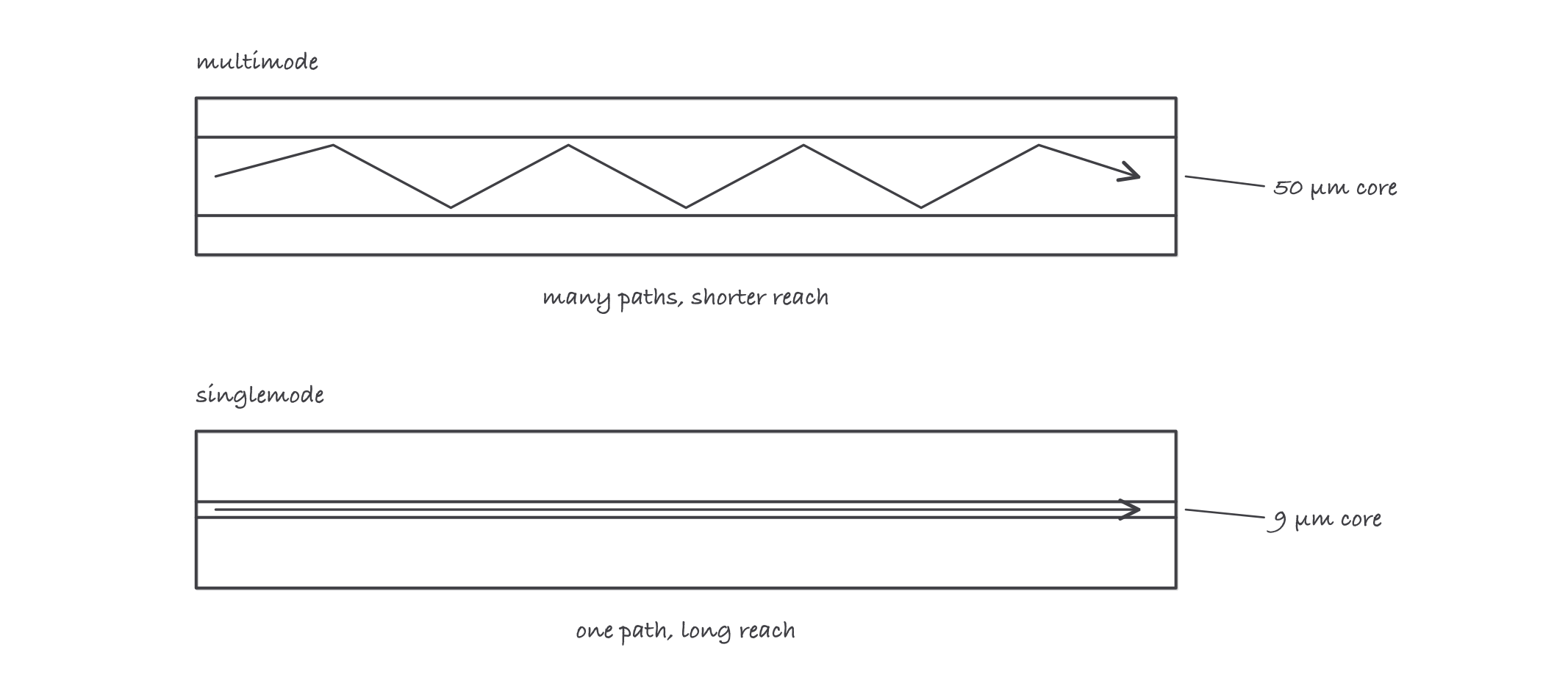
The core diameter is the identity of the fiber: many paths in multimode, one path in singlemode
Connectors you will meet daily: LC (small, dominant on modern equipment) and SC (larger, push-pull, common in older plant). Every connector joint is a “mated pair” in loss terms.
Splicing
- Fusion splicing melts two fiber ends together in an arc splicer. Lowest loss, permanent, the standard for backbone and outside plant work.
- Mechanical splicing aligns two cleaved ends in a fixture with index-matching gel. Faster and cheaper per tool, higher loss per joint, used for restorals and low-count work.
Either way, the splice is only as good as the cleave, and the cleave is only as good as your prep.
Worked example: loss budget
A 300 m multimode backbone run at 850 nm, with a connector at each end and one fusion splice mid-route. Design allowances for this job: fiber loss 3.5 dB/km, 0.75 dB per mated connector pair, 0.3 dB per splice.
- Fiber: 0.3 km × 3.5 dB/km = 1.05 dB
- Connectors: 2 × 0.75 = 1.50 dB
- Splice: 1 × 0.3 = 0.30 dB
- Budget: 1.05 + 1.50 + 0.30 = 2.85 dB
The light source and power meter measure 1.9 dB of actual loss. 1.9 ≤ 2.85, so the link passes with 0.95 dB of margin. A result near or above budget sends you hunting, and the first suspect is always a dirty connector.
Where it bites
- Never look into a fiber end. Infrared laser light is invisible and can damage your eye before you sense anything. Use a power meter or scope, never your face.
- Contamination is the number one cause of loss and failures. Inspect and clean every connector before mating, every time, even brand new ones out of the bag.
- Bend radius is a real limit. Glass does not complain when you overbend it; it leaks light now and cracks later. Macrobends show up as mystery loss.
- Mixed core sizes look identical from the outside. Jacket color conventions help (and lie); labels and documentation decide.
Exam relevance
The BICSI INSTF (Installer 2, Optical Fiber) credential covers this scope: fiber types, connectorization, splicing methods, and loss testing. Exams reward knowing the singlemode/multimode distinction cold and being able to add up a loss budget exactly like the worked example above.