Learn · Low Voltage and Telecom
Cable Certification Testing
Assumes you know: Copper: Categories, Termination, Testing, Fiber Optics: Types, Splicing, Testing
Certification testing measures an installed link against a published standard’s limits and returns a pass or fail with margins. It is a different act from verification (a wiremap check that the pins connect) or qualification (will this cable carry a given service). Certification is the test with legal and warranty weight: a certifier applies the limit set for the claimed category, measures, and records how much headroom the link has.
Why it matters on the job
Nobody gets paid on “it looks fine”. Manufacturers’ warranties and project acceptance both hang on certification reports, one per link, archived. The technician who understands what each measurement means can also do something the tester cannot: fix the failure. The tester tells you a pair failed near-end crosstalk at 7 m from the main unit; you have to know that means a bad termination in the patch panel, not 90 m of bad cable.
What the tester measures
A copper certifier is two units, main and remote, one at each end of the link. The core measurements:
- Wiremap: every pin lands where it should, no opens, shorts, or crossed or split pairs.
- Length: computed from the signal’s travel time and the cable’s NVP (nominal velocity of propagation), checked against the 90 m permanent link limit.
- Insertion loss: how much signal the run eats end to end. Lower is better.
- NEXT (near-end crosstalk): how much a transmitting pair bleeds into its neighbors at the near end. Higher measured dB is better: it means less coupling.
- Return loss: signal reflected back by impedance roughness, mostly from terminations.
Each result carries a margin: measured value minus the limit. Small margins get flagged as marginal passes, usually marked with an asterisk, and a professional treats those as work to redo, not wins.
Fiber has two tiers. Tier 1 is a light source and power meter: total loss against the budget, the pass/fail test. Tier 2 adds an OTDR trace that maps loss along the length, showing each splice and connector as an event, which is how you find where a failing link is failing.
Worked example: reading a copper report
A Cat6A permanent link report shows, for the worst pair at the worst frequency:
- Length: NVP-derived length 87 m ≤ 90 m limit. Pass.
- NEXT: limit 35.3 dB, measured 41.1 dB. Margin = 41.1 − 35.3 = +5.8 dB. Pass with comfortable headroom.
- Insertion loss: limit 24.0 dB, measured 21.6 dB. Margin = 24.0 − 21.6 = +2.4 dB. Pass.
- Return loss on pair 3-6: limit 12.0 dB, measured 12.4 dB. Margin +0.4 dB: a pass, but marginal. The fix is almost always re-terminating; the report even localizes the reflection near the outlet end.
One number out of limit anywhere and the link fails as a whole. Fix, retest, archive the clean report.
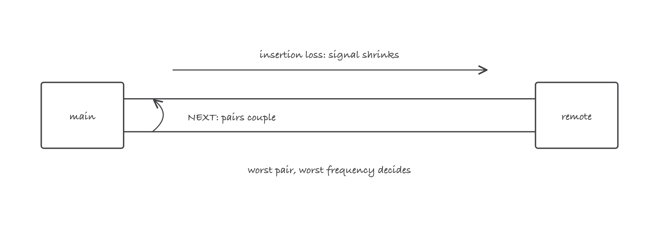
The two enemies the tester quantifies: the signal you lose along the run, and the neighbor’s signal you pick up at the near end
Where it bites
- Wrong NVP, wrong length. Set the tester to the installed cable’s NVP or watch good 88 m links “fail” at 93 m.
- Wrong limit set, meaningless report. Testing a permanent link with channel adapters and limits (or the reverse) produces confident nonsense. Match adapters, limits, and what you actually built.
- Marginal passes cluster at terminations. Re-terminate before you condemn cable: the panel and the jack are 10 minutes; a re-pull is an afternoon.
- Fiber testing fails on dirt. Inspect and clean before every mating, including the tester’s own reference cords, or the report measures your grime.
Exam relevance
The BICSI Technician (TECH) credential is the field-testing credential of the installer ladder: a two-part exam with a 14-task hands-on portion (20 minutes per task) and a 100-question, 2-hour written exam drawn from BICSI’s installation methods manual. Certification testing, reading margins, and diagnosing failures from report data sit squarely inside that scope.