Learn · Low Voltage and Telecom
Fire Alarm Circuits (NAC, SLC, IDC)
Part of Fire Alarm Technician, NICET Track · step 3 of 11 · next: NFPA 72 Basics
In learning paths: Fire Alarm Technician, NICET Track
Assumes you know: Initiating Devices and Notification Appliances
A fire alarm system runs on three kinds of circuits, named for what they do, not what they are made of: initiating device circuits (IDC) carry detection signals from conventional devices, signaling line circuits (SLC) carry digital data between the panel and addressable devices, and notification appliance circuits (NAC) carry power to horns and strobes. Layered on top, NFPA 72 classifies the pathways themselves (Class A, B, N, X) by how they survive faults. Circuit function plus pathway class describes any fire alarm wiring you will ever meet.
*Learn the Trades is a free study resource. We are not a licensing body, an authorized training provider, or an exam administrator. Reading this page does not award any card, license, or certification. Always verify requirements with the issuing authority linked in the sources.*Why it matters on the job
Every install, every troubleshoot, and every NICET fire alarm exam runs through this material. When a panel shows a trouble on “NAC 2” or an open on an SLC loop, the technician who knows what each circuit carries, and how it is supervised, finds the fault in minutes. This is also the single most heavily baited topic in exams: questions hinge on which circuit does what.
The three circuit functions
- IDC (initiating device circuit): the conventional detection loop. Devices are switches; any one closing puts the whole zone in alarm. The panel knows the zone, never the device: “second floor east” is as precise as an IDC gets.
- SLC (signaling line circuit): the addressable data loop. The panel polls each device by address, so it knows exactly which detector tripped, and it can carry many devices and even control modules on one pair.
- NAC (notification appliance circuit): the output circuit that powers horns and strobes when the panel calls the alarm. Quiet until needed, and supervised while quiet.
Supervision: the trickle that proves the wire
A fire alarm circuit must announce its own failure. On a conventional Class B circuit, the panel drives a small supervision current through the wiring to an end-of-line (EOL) resistor at the far end. Normal current means the path is intact; zero current means an open conductor; a jump in current means an alarm (a device shorted the loop) or a fault. NACs supervise the same way with polarity reversed: the supervision current passes through the EOL around the appliances, and alarm reverses polarity to drive them.
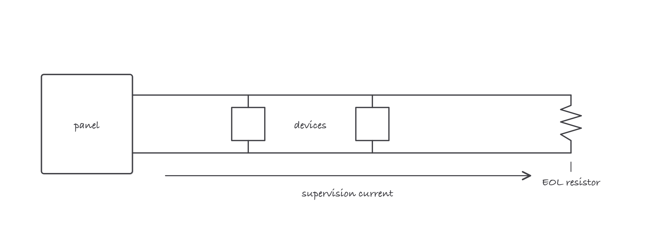
The EOL resistor sits at the electrical end of the line: current through it proves every meter of conductor between it and the panel
This is why T-taps are prohibited on Class B circuits: a branch beyond the tee is invisible to supervision, and a break in it is a silent hole in the safety net.
Pathway classes
- Class B: a single path with an EOL. An open is detected, but devices past the break stop working until it is fixed.
- Class A: the circuit loops back to the panel on a separate return path, so a single open leaves every device operating while trouble annunciates.
- Class N and Class X extend the scheme to network pathways and to Class A with added fault tolerance, respectively; you will meet them in the code’s pathway chapter.
Worked example: loading and voltage drop on a NAC
A NAC rated 3.0 A at 24 V serves 6 horn/strobes drawing 0.065 A each in alarm, at the end of a 46 m (150 ft) run of 14 AWG pair with a conductor resistance of 8.28 Ω per 1,000 m.
- Load: 6 × 0.065 = 0.390 A ≤ 3.0 A. The circuit carries it easily.
- Loop length: current goes out and back, so 2 × 46 = 92 m of conductor.
- Loop resistance: 92 ÷ 1,000 × 8.28 = 0.762 Ω.
- Voltage drop, worst case with all appliances at the end: 0.390 A × 0.762 Ω = 0.297 V.
- Check: with the panel at its end-of-battery minimum of 20.4 V, the appliances see 20.4 − 0.297 = 20.1 V, above the 16 V minimum on their listing. The circuit passes.
Real designs run this calculation with the appliance count and wire gauge of every NAC, and the derating values come from the equipment listings and the design documents.
Where it bites
- NAC, SLC, and IDC are functions, not wire types. The conductors can look identical on the reel. Supervision and function differ, and exams bait “which circuit” questions on exactly this.
- Three “class” systems collide here. NFPA 72 Class A/B/N/X pathways have nothing to do with NEC Class 2/3 power-limited circuits, and neither has anything to do with copper cable categories.
- An EOL in the panel is a lie. Move the EOL resistor to the panel for convenience and the circuit reads normal with every conductor cut. The EOL belongs at the electrical end of the line.
Exam relevance
Circuit functions, pathway classes, and supervision are core NICET fire alarm exam content from Level I up. Expect questions that name a symptom (open on an IDC, ground fault on an SLC, reversed polarity on a NAC) and ask what the panel shows, and questions that hand you a voltage-drop calculation shaped exactly like the worked example above.