Learn · Diesel Mechanics
Multiplexing and Scan Tool Diagnostics
Part of ASE T-Series Prep · step 10 of 20 · next: Preventive Maintenance and DOT Inspections
In learning paths: ASE T-Series Prep
Assumes you know: Truck Electrical and Electronic Systems
Multiplexing replaces bundles of dedicated wires with a shared data bus: dozens of control modules (engine, transmission, brakes, dash, body) talk over one twisted pair instead of each function owning its own copper. On heavy trucks the dominant language is SAE J1939, a controller area network (CAN) running on a two-wire backbone. Your scan tool is one more node on that network, which is why understanding the bus is the difference between reading codes and diagnosing trucks.
Why it matters on the job
When multiplexing works, it is invisible. When it fails, the symptoms are spectacular: a dash full of unrelated warning lights, ten modules reporting lost communication at once, gauges sweeping dead. Techs who do not understand the bus replace the modules that complained; techs who do measure the network in five minutes with an ohmmeter. At master level, network faults land on your bench.
How the bus works
The backbone is a twisted pair of wires (CAN high and CAN low) running the length of the chassis, with a terminating resistor of 120 ohms at each end. Modules connect to the backbone through short stubs. Every message carries an identifier, and every module hears every message, acting on the ones addressed to its job. Twisting the pair and driving the two wires as mirror images makes the network resistant to electrical noise, which matters on a machine full of alternators, solenoids, and two-way radios.
The termination does real work: the two 120 ohm resistors absorb signal reflections. Lose one and communications get flaky; lose both and the bus can go silent.
Fault codes speak SPN and FMI
J1939 diagnostics identify problems with number pairs:
- SPN (suspect parameter number) names what is being reported: a specific sensor, circuit, or value.
- FMI (failure mode identifier) names how it failed: voltage above normal, voltage below normal, data erratic, mechanical system not responding, and so on.
An SPN/FMI pair like “engine coolant temperature, voltage below normal” is a circuit description, not a command to replace the sensor. The FMI is the diagnostic gift: “voltage below normal” and “data valid but above normal range” send you down completely different paths for the same sensor.
Scan tool discipline
The scan tool shows every module’s view of the world. Use that: when one sensor’s value disagrees with physics (a 300 °F coolant reading on a cold engine), the FMI and the circuit own the problem. When many modules complain about one module, the bus segment or power feed to that module owns it. Record codes and freeze frames before clearing anything: cleared history is destroyed evidence, and adaptive systems relearn slowly.
Worked example: the 60 ohm check
The fastest network health check is resistance across the bus. Key off (network quiet), measure between CAN high and CAN low at the diagnostic connector.
Two 120 ohm terminators sit in parallel across the pair, so the healthy reading is: (120 × 120) ÷ (120 + 120) = 14,400 ÷ 240 = 60 ohms.
Read about 120 ohms and one terminator is missing: an end of the backbone is broken off, unplugged, or a terminating resistor has failed open. Read near 0 ohms and the pair is shorted together somewhere along the chassis. Read 60 ohms and the backbone wiring is probably fine, so a dead module’s own power, ground, or stub becomes the suspect.
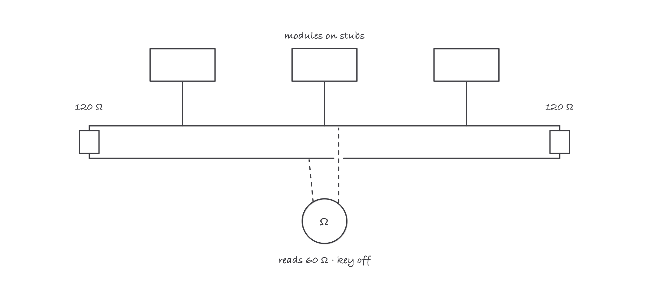
Two 120 ohm terminators in parallel: 60 ohms across a healthy quiet bus
Where it bites
- A module reported missing is usually a victim. “Lost communication with X” codes logged by other modules point at X’s power, ground, or stub, not at the modules doing the reporting.
- One screaming module can jam the whole bus. A failed transceiver can dominate the network and take every function down. Isolating modules one at a time (per the OEM procedure) finds the talker.
- Splices and connectors fail, not usually the wire. Corroded pins at chassis connectors and aftermarket add-ons spliced into the backbone are the classic J1939 killers. Ask what was installed last.
- Voltage checks lie on a live bus. The bus is differential; simple DC readings vary with traffic. Trust the resistance check on a quiet network and an OEM-specified procedure beyond that.
- Clearing codes is not a repair. On a network, a cleared code erases the map of which module saw what, in what order. Photograph first, clear last.