Learn · Diesel Mechanics
Truck Electrical and Electronic Systems
Part of ASE T-Series Prep · step 9 of 20 · next: Multiplexing and Scan Tool Diagnostics
In learning paths: ASE T-Series Prep
A truck’s electrical system is a 12 volt system asked to do brutal work: spin a high-compression diesel over on a January morning, feed a sleeper cab all night, and power dozens of computers, all through connections that live in salt spray and vibration. The fundamentals are batteries, cranking circuit, charging circuit, and the wiring that ties them together, and the master skill across all of them is the voltage drop test.
Why it matters on the job
Batteries get replaced for cable problems, starters for ground problems, alternators for belt problems. The tech who measures voltage drops instead of guessing owns this work, because the truck will always tell you where the resistance is if you ask it under load.
Batteries: a team with a weakest member
Trucks carry multiple batteries in parallel (commonly three or four) to supply cranking current and sleeper loads. Parallel wiring means they act as one big battery, and it also means one failing battery drags the pack down to its level, quietly discharging its healthy neighbors. Test batteries individually, not as a pack: a pack test averages the good ones over the bad one.
Battery boxes are a hostile environment: check hold-downs (vibration kills plates), terminals (corrosion is resistance), and cable condition where the insulation disappears into the box.
Cranking and charging
The starter circuit moves several hundred amps, so it is built from short fat cable and demands near-zero resistance. The key switch only signals; a relay or solenoid closes the heavy circuit.
The alternator recharges the pack and carries the running loads. Charging voltage on a healthy 12 volt system sits in the mid-14s at the battery, per the manufacturer’s spec. Low charging voltage at the batteries with good voltage at the alternator output post is not an alternator problem: it is cable resistance between the two, which is exactly what a voltage drop test finds.
The voltage drop test
Resistance you cannot see (a corroded crimp, a rusty ground, a “clean-looking” terminal) shows itself as voltage lost across a connection while current flows. Put a voltmeter across a section of circuit (positive cable end to end, or ground path end to end) and operate the load. The meter reads the volts consumed by that section. No load, no reading: a corroded cable measures fine sitting still.
The habit that makes this work: test the ground side as often as the positive side. Ground paths carry the same current as the positive side and corrode the same way, and they produce the weirdest symptoms, because current denied its ground finds creative paths through gauges, sensors, and modules.
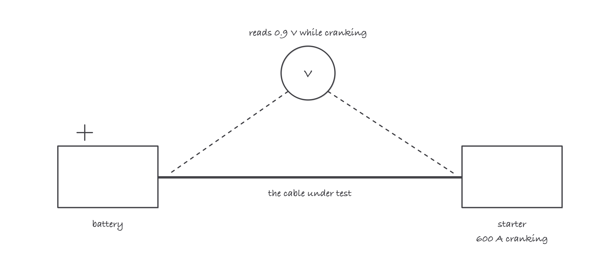
The drop only appears under load: crank the engine and the meter shows what the cable is stealing
Worked example: finding a bad cable with arithmetic
A truck cranks slowly. Batteries test good individually. While cranking, a voltmeter across the positive cable run (battery post to starter post) reads 0.9 V. Cranking current on this circuit is about 600 A.
The cable’s resistance: R = V ÷ I = 0.9 ÷ 600 = 0.0015 Ω, or 1.5 milliohms.
Sounds tiny. But suppose the service spec allows no more than 0.5 V of drop on this side of the circuit. At 600 A, that spec expects 0.5 ÷ 600 = 0.00083 Ω, about 0.83 milliohms. This cable run has nearly double the allowed resistance, and it is converting 0.9 V × 600 A = 540 watts into heat somewhere in a crimp while robbing the starter of the same power.
The fix is at whichever joint holds the drop: move one meter lead progressively along the run (post to clamp, clamp to cable, cable to starter) and the section still showing the voltage is the bad joint.
Where it bites
- A battery that “tests good” at rest can still be the problem. Surface charge and open-circuit voltage flatter a weak battery. Load-test or conductance-test each battery separately.
- Voltage at both ends proves nothing without load. An open circuit reads full battery voltage right up to the break. Current must flow for a drop test to speak.
- Grounds fail more than positives. Frame paint, corroded frame-to-engine straps, and add-on accessories grounded to nothing are behind a huge share of “impossible” electrical complaints.
- Modern trucks never sleep. Modules draw key-off current, and a parasitic draw above spec kills batteries on trucks parked over a weekend. Measure key-off draw after the modules time out, not the minute you clamp on.
- Do not load-test or weld without protecting the electronics. High current events and disconnected batteries while running can spike sensitive modules. Follow the OEM’s procedures for welding and jump-starting.